Overview
For the visualization of movements, the positions can be recorded and visualized via different interfaces.
Normally the axis position are reported in the display data. For the visualization of the contour the cyclic sampling of the positions is not sufficient. Real corners of the contour also in the visualization should be recognizable as corners. Even if the visualization is running much faster than the normal execution and only a low amount of sample points are reported the corners shall be displayed correct.
Different operation modes of contour visualization
rapid contour visualization without real axis movement
If the control is working in simulation mode the execution of the CNC-program is done rapidly. The contour is sampled and the coarse points are reported for visualization. The actual corners are also reported.
The amount of sample points is decreased considerably.
The real axis are not moved.
Online contour
visualization
The control is working in standard execution mode, where the normal program execution is not influenced.
Additionally axis position are reported via the interface to the contour visualization, if it is required.
Scene
The kinematic chain is defined in the CNC program. At any coordinate system of the kinematic chain (LINKPOINT) one of many graphical objects can be placed. The movements of the coordinate systems are reported through an interface. The movements of the graphical objects can be visualized by kernelCAM and the movement track of the objects can be recorded.
 | Functionality scene is not available under TwinCAT. |
|
Execution mode |
Data reduction before interpolation |
Data reduction after interpolation |
Coordinate system |
Particularity |
Viewer |
|---|---|---|---|---|---|
|
Dry run |
- none - |
- none - |
PCS |
Without real axis movement, normal program execution |
|
|
Rapid contour visualization |
Geometric grid, abs./rel. secant error |
Geometric grid, abs./rel. secant error |
PCS / ACS by channel parameter |
Without real axis movement, rapid program execution |
kernelCAM in preparation |
|
Online contour visualization |
- none - |
Geometric grid, abs./rel. secant error |
PCS / ACS by channel parameter |
|
kernelCAM in preparation |
|
Scene |
- none - |
Time sampling in frames per second |
W0 Each coordinate sytem of the kinematic chain, also TCP |
For any serial kinematic available. Kinematic chain must be defined in the NC-Program |
kernelCAM as virtual CAM (vCAM) |
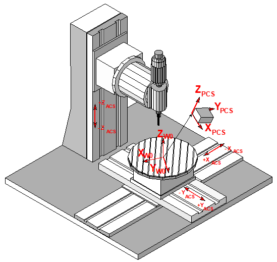
Coordinate systems
The interfaces provide movements in different coordinate systems. Following definition of coordinate systems is used:
|
|
|
|
ACS |
Axis coordinate system |
|
W0 |
Base workpiece coordinate system, kartesian base coordinate system of machine, corresponding to work piece clamp position |
|
PCS |
Programming coordinate system |