Helical mill drilling
In the case of helical mill drilling, the tool moves to the specified machining depth at the selected spindle speed and feed rate in a helical motion G02/G03. The hole is produced in one operation down to the final drilling depth. The end point on the first and the second main axis is calculated internally in the cycle. After that, the tool returns to the specified return plane without a dwell time in the rapid traversing mode G00. Optionally, a flat mill recess can be ordered for the basic hole at the end of the helical drilling operation. With this method, it is therefore possible to create a hole (or a basic hole) whose diameter is greater than the milling cutter's diameter.
The following parameters are required for calling of a helical mill drilling operation:
Cycle parameters | Description |
|---|---|
@P1 | Retraction plane (absolut) |
@P2 | Reference plane (absolut) |
@P3 | Safety clearance (relative to the reference plane, unsigned) |
@P4 | Final drilling depth (absolute) or... |
@P5 | ...Final drilling depth (relative to the reference plane, unsigned) |
@P6 | Radius of the helical motion (unsigned) |
@P7 | Pitch of the helical motion (unsigned) |
@P8 | Direction of rotation (G02->(2), G03->(3)) |
@P9 (optional) | Surface milling, basic (optional, helical only->(0), helical+basic->(1)) |
@P10 | Machining direction (for offsetting the safety clearance) |
Syntax:
L CYCLE [NAME=helimill.cyc @P1=.. @P2=.. @P3=.. @P4=.. | @P5=.. @P6=.. @P7=.. @P8=.. @P9=.. @P10=.. ] 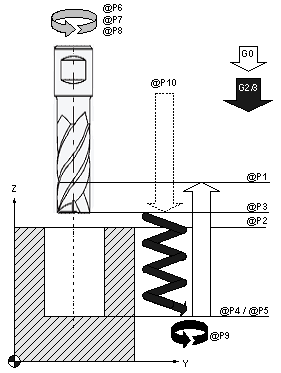 Fig.8: Helical mill drilling sequence
Programming example
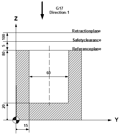
(Creation of a basic hole)
N10 T9 D9 Current tool data
N20 M6 Tool change
N30 G00 G17 G90 M03 S10000 Technology values
N40 Z100 Travel to retraction plane
N50 Y15 X0 F800 G41 Mill drilling position
N60 L CYCLE [NAME=helimill.cyc @P1=100 @P2=80
@P3=5 @P4=20 @P6=30 @P7=1 @P8=3
@P9=1 @P10=-1]
N70 G00 Z150 M5 Parking position,spindle stop
N80 M30 Program end