Deep hole drilling
In the case of deep hole drilling, the tool drills at the selected spindle speed and feed rate G01 in multiple-step operations down to the specified machining depth, and the number of infeed operations is programmable. Internally in the cycle, the resulting infeed depth is determined based on the final drilling depth.
Two different execution methods can be selected via the corresponding parameters' assignments.
Breaking chips
In the case of the first one, after every infeed depth the drill is withdrawn by a programmed distance for chip breaking.
Discharging chips
In the case of the second one, the drill is moved out of the hole to the reference plane + safety clearance after every infeed depth to discharge chips.
Once the final drilling depth has been reached, the tool returns to the specified retraction plane after expiry of a programmed dwell time in the rapid traversing mode G00.
The following parameters are required for calling of a deep drilling hole:
Cycle parameters | Description |
|---|---|
@P1 | Retraction plane (absolut) |
@P2 | Reference plane (absolut) |
@P3 | Safety clearance (relative to the reference plane, unsigned) |
@P4 | Final drilling depth (absolute) or... |
@P5 | ...Final drilling depth (relative to the reference plane, unsigned) |
@P6 (optional) | Dwell time at final drilling depth |
@P7 | Number of infeeds |
@P8 | Return distance for chip breaking or holding distance after chip discharge (unsigned) |
@P9 | Process (chip breaking (1), chip discharging (2)) |
@P10 | Machining direction (for offsetting the safety clearance) |
Syntax:
L CYCLE [NAME=drilling.cyc @P1=.. @P2=.. @P3=.. @P4=.. | @P5=.. @P6=.. @P7=.. @P8=.. @P9=.. @P10=..] Feed depth and feed
Internally in the cycle, the value of one single drilling stroke (feed depth) is determined via the number of feed operations.
During each feed operation, feed rate degression by a factor of 0.9 is realized. As a result, chips can flow off better and the risk of tool breakage can be minimized.
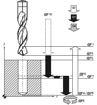 Fig.5: Sequence of deep hole drilling with chip breaking (@P9=1)
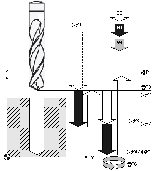 Fig.6: Sequence of deep hole drilling with chip discharge (@P9=2)
Programming example
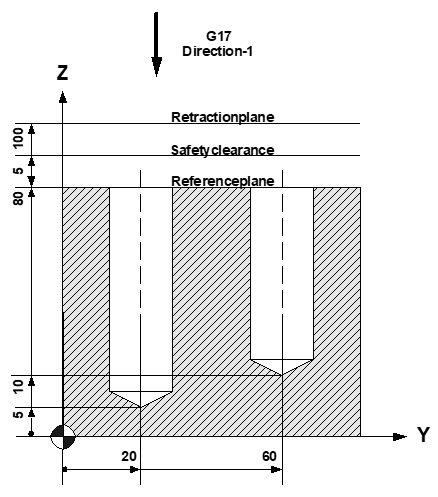
(Creation of 2 centring holes)
N10 T4 D4 Current tool data
N20 M6 Tool change
N30 G00 G17 G90 F250 M03 S400 Technology values
N40 Z100 Travel to retraction plane
N50 Y20 X0 1st drilling position
(1st deep hole drilling in 3 steps, with chip discharge and absolute final drilling depth)
N60 L CYCLE [NAME=drilling.cyc @P1=100 @P2=80
@P3=5 @P4=5 @P6=1 @P7= 3 @P8=0.5
@P9=2 @P10=-1]
N70 Y60 X0 2nd drilling position
(2nd deep hole drilling in 2 steps, with chip breaking and relative final drilling depth)
N80 L CYCLE [NAME=drilling.cyc @P1=100 @P2=80
@P3=5 @P5=70 @P6=1 @P7= 2 @P8=0.5
@P9=1 @P10=-1]
N90 Z200 M5 Parking position, spindle stop
N100 M30 Program end