Through/centering hole
In the case of a thorough/centering hole, the tool drills to the specified machining depth at the selected spindle speed and feed rate G01. The hole is produced in one operation down to the final drilling depth. After that, the tool returns to the specified retraction plane after expiry of an optionally programmed dwell time for chip breaking in the rapid traversing mode G00.
The following parameters are required for calling of a thorough/centering hole:
Cycle parameters | Description |
|---|---|
@P1 | Retraction plane (absolut) |
@P2 | Reference plane (absolut) |
@P3 | Safety clearance (relative to the reference plane, unsigned) |
@P4 | Final drilling depth (absolute) or... |
@P5 | ...Final drilling depth (relative to the reference plane, unsigned) |
@P6 (optional) | Dwell time at final drilling depth |
@P10 | Machining direction (for offsetting the safety clearance) |
Syntax:
L CYCLE [NAME=drilling.cyc @P1=.. @P2=.. @P3=.. @P4=.. | @P5=.. @P6=.. @P10=..] 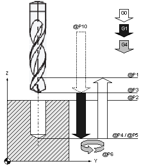 Fig.3: Through/centering hole sequence
Programming example
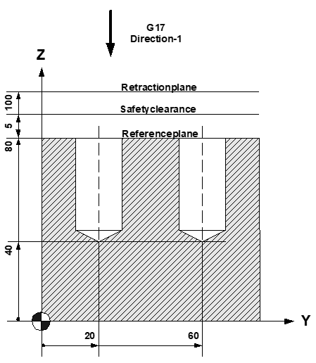
(Creation of 2 centring holes)
N10 T5 D5 Current tool data
N20 M6 Tool change
N30 G00 G17 G90 F250 M03 S400 Technology values
N40 Z100 Travel to retraction plane
N50 Y20 X0 1st drilling position
N60 L CYCLE [NAME=drilling.cyc @P1=100 @P2=80
@P3=5 @P4=40 @P6=1 @P10=-1]
N70 Y60 X0 2nd drilling position
N80 L CYCLE [NAME=drilling.cyc @P1=100 @P2=80
@P3=5 @P4=40 @P6=1 @P10=-1]
N90 Z200 M5 Parking position, spindle stop
N100 M30 Program end