Structure
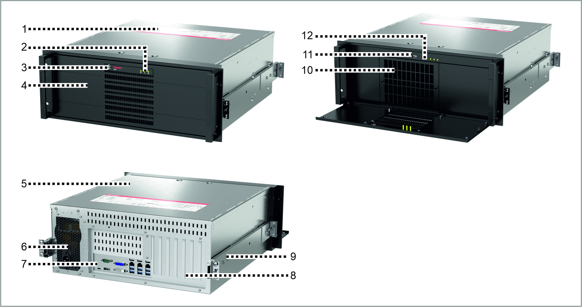 Fig.1: Structure
No. | Component | Description |
|---|---|---|
1 | Name plate | Information on the equipment of the industrial PC |
2 | Status LEDs | Status display for hard disk, fieldbus and power |
3 | Front flap lock | Opening the front flap |
4 | Front flap | Access to ATX and reset button, USB interfaces, drives, removable frame, front fan filter mat |
5 | Housing cover | Access to exchangeable device components |
6 | Power supply | Power supply connection |
7 | Connection section | Access to interfaces of the industrial PC |
8 | Plug-in card slots | Additional optional plug-in cards |
9 | Optional telescopic rails | Pull-out rails for installation in 19-inch racks |
10 | Front fan with filter mat | Cooling the device |
11 | USB interfaces (X212, X213) | Connection of peripheral devices |
12 | ATX and reset button | Starting and shutting down the operating system, restarting the industrial PC |