Structure
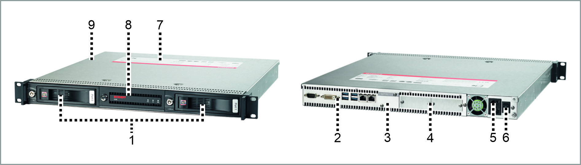 Fig.1: Structure
No. | Component | Description |
|---|---|---|
1 | Removable frame | Access to hard disk/SSD |
2 | Connection section | Access to interfaces |
3 | Battery cover | Access battery and optional fieldbus interface |
4 | PCIe® module slots | Optional interface expansion with PCIe® modules |
5 | IEC socket | Power supply connection |
6 | Main switch | Switching the device on/off |
7 | Name plate | Information on the equipment of the device |
8 | Front flap | Access USB interfaces, ATX button, reset button, status LEDs |
9 | Housing cover | Access to replaceable fans |