IclA drive at SSB
Required material:
- TwinCAT 2.9 build 953 or higher
- BX3100 version 0.80 or higher
- 1 x KL1xx4
- 1 x KL2xx4
- 1 x KL9010
- 1 x IclA D065 with the following settings: slave address 10, baud rate 500 kbyte (Please note: These are not the default parameters of the drive)
- Cabling material and power supply
For the configuration download via ADS, either a BECKHOFF fieldbus master or a free serial port is required.
Reconfiguration example for TwinCAT with FC510x CANopen master card
An example for converting a drive is listed below.
- TwinCAT System Manager file (sample file)
-

- TwinCAT PLC file (sample file)
-
baudratefc510x.wsm
setbaudratefc510x.pro
Example program and configuration on the BX Controller
- TwinCAT System Manager file (sample file)
-
(The System Manager file has to be transferred to the BX Controller via ADS).
- BX program file (sample file)
-
icla_example.tsm
icla_example.prx
IclA D065 description
The following sections are extracts from the IclA drive manual. They were provided by the company SIG Positec Automation GmbH for the purpose of describing the basic parameters. Further information can be found on the internet at http://www.sig-positec.de.
Hardware and interfaces
- Signal interface for
- Supply voltage
- Control signals for manual mode
- Connection for emergency stop signal
- Protective conductor connection for earthing via PE bus bar
- Fieldbus connection for connecting the fieldbus cable.
If the emergency stop function is not required, connect pin 2 with pin 8 or 9 (24 VDC).
Control word 0x6040
The object represents the control word for the device. The control word is used for several control tasks:
- Changeover between different operating states. The possible states and transitions can be found under the index keyword "machine state". Bits 0 to 3 and bit 7 are relevant for a change of state.
- Starting and stopping mode-specific functions, e.g. starting a travel command via bit 4. Bits 4 to 6 are used for mode-specific settings. Further details can be found under the keywords "Operating mode, starting", "Operating mode, monitoring" and in the description of the respective operating modes in sections "Manual mode" and "Positioning mode".
- Stopping of the positioning drive from an active travel operation. Bit 8 "Stop" is used for stopping. Further details can be found under the keywords "Operating mode, starting" and "Operating mode, monitoring".
|
Object description |
Value description |
|---|---|
|
Index |
6040h |
|
Object name |
Control word |
|
Data type |
Integned16 |
|
Subindex |
00h, control word |
|
Access |
read-write |
|
PDO-Mapping |
R_PDO |
|
Bit |
Name |
Meaning |
|---|---|---|
|
11..15 |
Manufacturer specific |
not used |
|
9, 10 |
- |
reserved |
|
8 |
Stop |
Stop motor |
|
7 |
Reset fault |
Reset fault |
|
4..6 |
- |
Operating mode dependent, |
|
3 |
Enable operation |
Execute operating mode |
|
2 |
Quick stop (low active) |
Breaking with quick stop ramp |
|
1 |
Disable voltage (low active) |
Switch off voltage |
|
0 |
Switch on |
Switch into ready-to-run state |
Status word 0x6041
The object describes the current operating state of the device. The status word can be used for the following monitoring functions:
- Checking the operating state of the positioning controller. Bits 0 to 3, 5 and 6 are relevant.
- Bit 4 indicates whether the output stage is ready for processing a transport instruction.
- Bits 7 to 15 are used for monitoring the travel operation and for status monitoring of device-specific states.
Further details for monitoring travel operation can be found under the keywords "Operating mode, starting", "Operating mode, monitoring" and in the description of the respective operating modes in sections "Manual mode" and "Positioning mode". The bits for device status monitoring are described in section "Diagnostics and trouble shooting".
The control word is represented in the first two bytes of the R_PDOs.
|
Object description |
Value description |
|---|---|
|
Index |
6041h |
|
Object name |
Status word |
|
Data type |
Unsigned16 |
|
Subindex |
00h, status word |
|
Access |
read-only |
|
PDO Mapping |
T_PDO |
|
Bit |
Name |
Meaning |
|---|---|---|
|
15 |
Out of security area |
Out of security area |
|
14 |
Out of drive area |
Out of drive area |
|
12..13 |
- |
Operating mode-dependent meaning |
|
11 |
Internal limit active |
Out of working area |
|
10 |
Target reached |
Target reached |
|
9 |
Remote |
0: manual mode |
|
8 |
Right out of drive area |
Only valid if bit 11 = 1 |
|
7 |
Warning |
Warning |
|
6 |
Switch on disabled |
not ready for operation |
|
5 |
Quick Stop |
Quick stop active |
|
4 |
Voltage disabled |
Voltage off |
|
3 |
Fault |
Fault occurred |
|
2 |
Operation enabled |
Operating mode enabled |
|
1 |
Switched on |
Ready for operation |
|
0 |
Ready to switch on |
Ready to switch on |
Reference ranges
A valid referencing is defined via three limit switch zones, which have to be within the possible traversing range of the drive. The limit switches protect the drive and the system from damage.
- Working area W0 - W1 for positioning mode.
- Drive area D0 - D1. From ranges D0 - W0 and D1 - W1, the drive can
- only be moved backwards towards the operating range.
- Security area S0 - S1. From areas S0 - D0 and S1 - D1, the drive can only be moved backwards manually.
- CANopen objects - three CANopen objects are used for setting up the limit switches. They contain the position values for the upper and lower range limits.
- Working area limits in software position limit (607Dhex)
- Drive area limits in software position drive limit (2009hex)
- Security area limits in software position safety limit (2008hex)
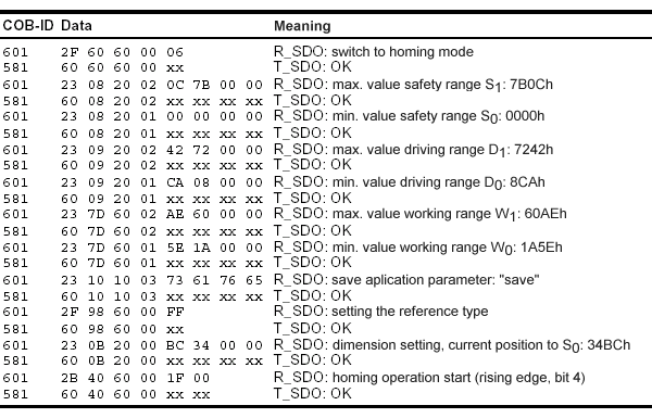
Referencing example
The following listing demonstrates the input of the referencing values. The node address of the positioning drive is set to 01hex.