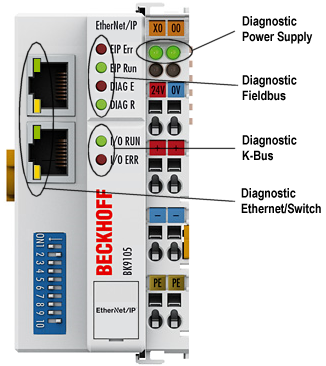
Diagnostic LEDs
After switching on, the Bus Coupler immediately checks the connected configuration. Error-free start-up is indicated when the red I/O ERR LED goes out. If the I/O ERR LED blinks, an error in the area of the terminals is indicated. The error code can be determined from the frequency and number of blinks. This permits rapid rectification of the error.
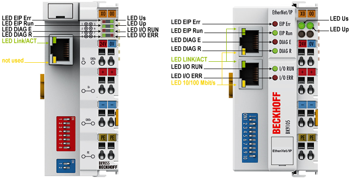
The Bus Coupler has two groups of LEDs for the display of status. The upper group with four LEDs indicates the status of the respective fieldbus. The significance of the fieldbus status LEDs is explained in the appropriate sections of this manual. It corresponds to the usual fieldbus display.
On the upper right hand side of the Bus Couplers are two more green LEDs that indicate the supply voltage. The left hand LED indicates the presence of the 24 V supply for the Bus Coupler. The right hand LED indicates the presence of the supply to the power contacts.
LEDs for power supply diagnosis
LED | Meaning | |
|---|---|---|
LED Us | off | The power supply voltage Us is not present |
on | The power supply voltage Us is present | |
LED Up | off | The power supply voltage Up (for Power Contacts) is not present |
on | The power supply voltage Up (for Power Contacts) is present | |
LEDs at RJ45
LED | Meaning | |
|---|---|---|
LED Link/Act | off | No physical connection present |
on | Physical connection present | |
flashes | Communication available | |
LED 10/100 Mbit/s | off | 10 Mbit/s (if LED Link/Act is shining or flashing) |
on | 100 Mbit/s | |
LEDs for fieldbus diagnosis
EtherNet/IP Diagnosis | EIP E (red) | EIP R (green) | DIAG E (red) | DIAG R (green) |
|---|---|---|---|---|
IP Address OK | off | 0,5s | x | x |
No IP Address (Dip Switch 8,9 -> on) | off | off | x | x |
Online | off | on | x | x |
Offline PLC Stop | off | 0,1s | x | x |
TimeOut | 0,5s | off | x | x |
IP Address conflict | on | off | x | x |
Configuration Diagnosis | EIP E (red) | EIP R (green) | DIAG E (red) | DIAG R (green) |
|---|---|---|---|---|
OK | x | x | off | on |
In data too less | x | x | Flashing* | 1 |
In data too big | x | x | Flashing* | 2 |
Out data too less | x | x | Flashing* | 3 |
Out data too big | x | x | Flashing* | 4 |
Wrong Assembly Instance | x | x | Flashing* | 5 |
Second Master | x | x | Flashing* | 6 |
*) Bytes are too less (missing) or to big
X: The status of the LED is not relevant for this diagnosis.
Example:
Data Length In too big 5 Bytes…
- Start Error Code: Red LED is quickly flashing, green LED is Off
- Red LED is ON, green LED show you the Error Code flashing 2 times (1 Sec)
- Red LED OFF, green LED off
- Red LED flashing 5 times (1 Sec), error argument, green LED off
LEDs for K-Bus diagnosis
Error code | Error | Description | Remedy |
|---|---|---|---|
Persistent, continuous blinking |
| EMC problems |
|
1 pulse | 0 | EEPROM checksum error | Set manufacturer’s setting with the KS2000 configuration software |
1 | Code buffer overflow | Insert fewer Bus Terminals. The programmed configuration has too many entries in the table | |
2 | Unknown data type | Software update required for the Bus Coupler | |
2 pulses | 0 | Programmed configuration has an incorrect table entry | Check programmed configuration for correctness |
n (n > 0) | Table comparison (Bus Terminal n) | Incorrect table entry | |
3 pulses | 0 | K-Bus command error |
|
4 pulses | 0 | K-Bus data error, break behind the Bus Coupler | Check whether the n+1 Bus Terminal is correctly connected; replace if necessary. |
n | Break behind Bus Terminal n | Check whether the Bus End Terminal KL9010 is connected. | |
5 pulses | n | K-Bus error in register communication with Bus Terminal n | Exchange the nth bus terminal |
6 pulses | 0 | Error at initialization | Exchange Bus Coupler |
1 | Internal data error | Perform a hardware reset on the Bus Coupler (switch off and on again) | |
2 | DIP switch changed after a software reset | Perform a hardware reset on the Bus Coupler (switch off and on again) | |
4 | DIP switch incorrect for BootP | Set 1-8 to on or off, see BootP | |
8 | Internal data error | Perform a hardware reset on the Bus Coupler (switch off and on again) | |
16 | Error in IP socket | Perform a hardware reset on the Bus Coupler (switch off and on again) | |
14 pulses | n | nth Bus Terminal has the wrong format | Start the Bus Coupler again, and if the error occurs again then exchange the Bus Terminal |
15 pulses | n | Number of Bus Terminals is no longer correct | Start the Bus Coupler again. If the error occurs again, restore the manufacturers setting using the KS2000 configuration software |
16 pulses | n | Length of the K-Bus data is no longer correct | Start the Bus Coupler again. If the error occurs again, restore the manufacturers setting using the KS2000 configuration software |