BK9105 - Introduction
The BK9105 Bus Coupler connects EtherNet/IP with the modular, extendable electronic terminal blocks. One unit consists of one Bus Coupler, any number from 1 to 64 terminals (255 with K-bus extension) and one end terminal.
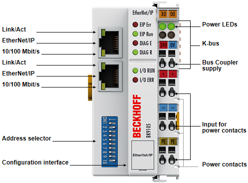
The Bus Coupler recognizes the terminals to which it is connected, and performs the assignment of the inputs and outputs to the words of the process image automatically. The BK9105 Bus Coupler supports 10 Mbit/s and 100 Mbit/s Ethernet. Connection is through normal RJ 45 connectors. The IP address is set on the DIP switch (offset to a freely selectable start address). In networks with DHCP (a service for the allocation of the logical IP address to the physical node address [MAC-ID]) the Bus Coupler obtains its IP address from the DHCP server.
The BK9105 contains a 3-port switch. Two ports operate external on RJ 45 connectors and can be utilized. The I/O stations can thus be configured with a line topology, instead of the classic star topology. In many applications this significantly reduces the wiring effort and the cabling costs. The maximum distance between two couplers is 100 m. Up to 20 BK9105 Bus Couplers are cascadable, so that a maximum line length of 2 km can be achieved.
Ethernet/IP is the Industrial Ethernet standard of ODVA (Open DeviceNet Vendor Association). Ethernet/IP is based on Ethernet TCP/IP and UDP/IP – IP stands for Industrial Protocol. Essentially, the CIP (Common Industrial Protocol) used in ControlNet and DeviceNet was ported to Ethernet TCP/IP and UDP/IP.
Complex signal processing for analog I/Os, position measurement …
The BK9105 Bus Coupler supports the operation of all Bus Terminal types.
The analog and multi-functional Bus Terminals can be adapted to each specific application using the KS2000 configuration set. Depending on the type, the analog Bus Terminals' registers contain temperature ranges, gain values and linearization characteristics. With the KS2000, the required parameters can be set on a PC. The Bus Terminals store settings permanently and in a fail-safe manner.
Optionally, the Bus Terminals can also be controlled by the control system. Via function blocks (FBs), the programmable logic controller (PLC) or the Industrial PC (IPC) handle configuration of the complete periphery during the start-up phase. If required, the controller can upload the decentrally created configuration data in order to centrally manage and store this data. Therefore, new adjustments are not necessary in the event of replacement of a Bus Terminal. The controller carries out the desired setting automatically after switching on.