Configuration example with Step 7
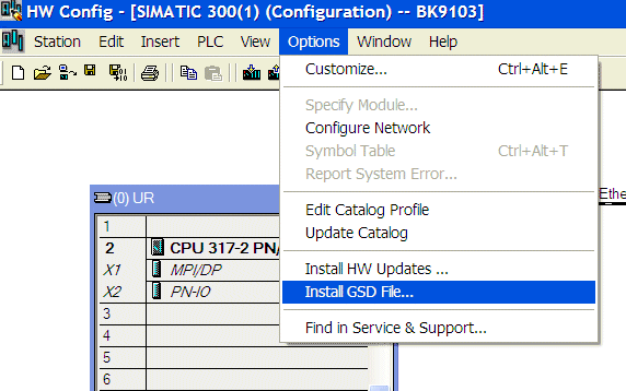
Install the GSDML file (Step 7 from version 5.4 + SP1)
To this end open the hardware manager. Install the GSDML file.
Add a BK9103 as a node in your Manager, then add the terminals according to your configuration.
Enter the name of the PN device, e.g. bk9103-1 (bk must be lower case).
Set DIP switches 1, 9 and 10 of the BK9103 to ON and all others to OFF, then switch on the Coupler).
The configuration will now look as follows, for example. Load the configuration into your control system.