Diagnostic LEDs
BK9000, BK9100, BC9000, BC9100
After switching on, the Bus Coupler immediately checks the connected configuration. Error-free start-up is indicated when the red I/O ERR LED goes out. If the I/O ERR LED blinks, an error in the area of the terminals is indicated. The error code can be determined from the frequency and number of blinks. This permits rapid rectification of the error.
The Bus Coupler has two groups of LEDs for the display of status. The upper group with four LEDs indicates the status of the respective fieldbus. The significance of the fieldbus status LEDs is explained in the appropriate sections of this manual. It corresponds to the usual fieldbus display.
On the upper right hand side of the Bus Couplers are two more green LEDs that indicate the supply voltage. The left hand LED indicates the presence of the 24 V supply for the Bus Coupler. The right hand LED indicates the presence of the supply to the power contacts.
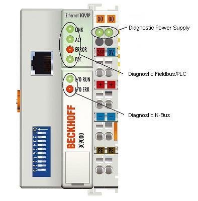
LEDs for power supply diagnostics
LED | Meaning |
|---|---|
Left LED off | Bus Coupler has no power |
Right LED off | No 24 VDC power supply connected to the power contacts |
LEDs for fieldbus diagnostics
LED | On | Off |
|---|---|---|
LINK (BK9000/BC9000 only) | Physical connection present | No physical connection present |
ACT (BK9000/BC9000 only) | Flashing: Bus traffic present | No bus traffic (bus idle) |
COM (BK9100/BC9100 only) | Flashing: data received at the controller | no data are received |
ERROR | The LED flashes slowly if DHCP or BootP is active but the Bus Coupler has not yet received an IP address LED permanently on (in RT-Ethernet mode only) | No error |
PLC (BC9000/BC9100 only) | PLC program is in RUN mode | PLC program is in stop mode |
WDG (BK9000 only) | Watchdog is triggered
| Watchdog expired or not triggered
|
LEDs for K-bus diagnostics
Error code | Error argument | Description | Remedy |
|---|---|---|---|
Persistent, continuous flashing |
| EMC problems |
|
1 pulse | 0 | EEPROM checksum error | Set manufacturer's setting with the KS2000 configuration software |
1 | Code buffer overflow | Insert fewer Bus Terminals. Too many entries in the table for the programmed configuration | |
2 | Unknown data type | Software update required for the Bus Coupler | |
3 | Process data to big | Reduce number of K-bus terminals | |
2 pulses | 0 | Programmed configuration has an incorrect table entry | Check programmed configuration for correctness |
n (n > 0) | Table comparison (Bus Terminal n) | Incorrect table entry | |
3 pulses | 0 | K-bus command error |
|
4 pulses | 0 | K-bus data error, break behind the Bus Coupler | Check whether the n+1 Bus Terminal is correctly connected; replace if necessary. |
n | Break behind Bus Terminal n | Check whether the bus end terminal 9010 is connected. | |
5 pulses | n | K-bus error in register communication with Bus Terminal n | Exchange the nth bus terminal |
6 pulses | 0 | Error at initialization | Exchange Bus Coupler |
1 | Internal data error | Perform a hardware reset on the Bus Coupler (switch off and on again) | |
2 | DIP switch changed after a software reset | Perform a hardware reset on the Bus Coupler (switch off and on again) | |
IP address already exists in the network | Assign a different IP address | ||
4 | DIP switch incorrect for BootP | Set 1-8 to on or off, see BootP | |
8 | Internal data error | Perform a hardware reset on the Bus Coupler (switch off and on again) | |
16 | Error in IP socket | Perform a hardware reset on the Bus Coupler (switch off and on again) | |
7 pulses (BC9000/BC9100 only) | 0 | Note: cycle time was exceeded | Warning: the set cycle time was exceeded. This note (flashing of the LED) can only be reset by rebooting the BC. |
9 pulses (BC9000/BC9100 only) | 0 | Checksum error in Flash program | Transmit program to the BC again |
1 | Incorrect or faulty library implemented | Remove the faulty library | |
10 pulses (BC9000/BC9100 only) | n | Bus Terminal n is not consistent with the configuration that existed when the boot project was created | Check the nth Bus Terminal. The boot project must be deleted if the insertion of an nth Bus Terminal is intentional |
14 pulses | n | nth Bus Terminal has the wrong format | Start the Bus Coupler again, and if the error occurs again then exchange the Bus Terminal |
15 pulses | n | Number of Bus Terminals is no longer correct | Start the Bus Coupler again. If the error occurs again, restore the manufacturers setting using the KS2000 configuration software |
16 pulses | n | Length of the K-bus data is no longer correct | Start the Bus Coupler again. If the error occurs again, restore the manufacturers setting using the KS2000 configuration software |
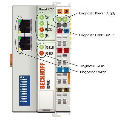
LEDs for switch diagnosis (BK9100/BC9100 only)
LED | On | Flashes | Off |
|---|---|---|---|
LINK/ACT | Physical connection present | Communication available | No physical connection present |
10/100 Mbaud | 100 Mbaud | - | 10 Mbaud |