BK9000, BK9050 – Introduction
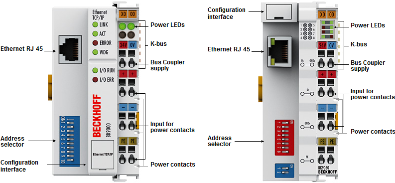
The BK9000 and BK9050 Bus Couplers connect Ethernet with the modular, extendable electronic terminal blocks. One unit consists of one Bus Coupler, any number from 1 to 64 terminals and one end terminal. The "Compact" BK9050 Bus Coupler is a cost-optimized version with compact housing. With the K-bus extension, up to 255 Bus Terminals can be connected.
The Bus Couplers recognize the terminals to which they are connected, and perform the assignment of the inputs and outputs to the words of the process image automatically. The BK9000 and BK9050 Bus Couplers support 10 Mbit/s and 100 Mbit/s Ethernet. Connection is through normal RJ 45 connectors. The IP address is set on the DIP switch (offset to a freely selectable start address). In networks with DHCP (a service for the allocation of the logical IP address to the physical node address (MAC-ID)) the Bus Coupler obtains its IP address from the DHCP server.
The BK9000 and BK9050 Bus Couplers support ADS TwinCAT system communication. TwinCAT I/O makes available configuration tools and Windows-NT//2000/XP drivers for programs in any desired high-level language (DLLs) and for Visual Basic applications (ActiveX). Applications with OPC interfaces can access ADS (and therefore the BK9000 or BK9050) via an OPC server. In addition to ADS the Bus Coupler supports Open Modbus (Modbus TCP), a simple master/slave protocol based on TCP/IP in wide application.
Complex signal processing for analog I/Os, displacement measurement, etc.
The BK9000 and BK9050 Bus Couplers support the operation of all Bus Terminal types. As far as the user is concerned, the inputs and outputs are not handled any differently from the way they are with other coupler series. The information is made available for use as a byte array in the process image of the automation device.
The KS2000 configuration software allows the analog and multifunctional Bus Terminals to be adapted to the specific application. Depending on the type, the registers of the analog Bus Terminals contain temperature ranges, gain factors and linearization characteristic curves, which are parameterized via the PC using the KS2000. The Bus Terminal stores the setting permanently, even if the voltage supply fails.
Having the controller (PLC, IPC) carry out the configuration of the Bus Terminals is a further option. The PLC or IPC uses function blocks (FB) to take care of the configuration of all the peripherals during the start-up phase. The controller can, if required, upload the non-centrally generated configuration data in order to manage and store them centrally. The replacement of a Bus Terminal does not necessitate new settings. The controller carries out the desired setting automatically after switching on.