Composition of a process image in the Bus Coupler
An example shows the assignment of input and output channels to the process image. The sample construction should consist of the following bus - terminal - assemblies:
Position | Functional groups on the rail |
|---|---|
POS01 | Bus Coupler |
POS02 | Digital inputs, 2 channels |
POS03 | Digital inputs, 2 channels |
POS04 | Digital inputs, 2 channels |
POS05 | Digital inputs, 2 channels |
POS06 | Digital inputs, 2 channels |
POS07 | Digital outputs, 2 channels |
POS08 | Digital outputs, 2 channels |
POS09 | Digital outputs, 2 channels |
POS10 | Analog inputs, 2 channels |
POS11 | Analog outputs, 2 channels |
POS12 | Analog outputs, 2 channels |
POS13 | Analog inputs, 2 channels |
POS14 | Power feed terminal |
POS15 | Digital inputs, 2 channels |
POS16 | Digital inputs, 2 channels |
POS17 | Digital inputs, 2 channels |
POS18 | Digital outputs, 2 channels |
POS19 | Digital outputs, 2 channels |
POS20 | Analog outputs, 2 channels |
POS21 | End terminal |
By default, DeviceNet only supports signal channels that are 16 bits wide. The STATUS/CONTROL BYTE is not available. This means, for example, that an analog input terminal with 2 channels appears in the process image with 2 x 16 bits. The images have corresponding differences with respect to byte addresses and assignments.
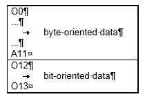
Area for byte-oriented data, analog outputs
Relative byte address | Bit position | Process image in the controller | Position in the block |
|---|---|---|---|
0, 1 | none | O0, O1 | POS11 |
2, 3 | none | O2, O3 | POS11 |
4, 5 | none | O4, O5 | POS12 |
6, 7 | none | O6, O7 | POS12 |
8, 9 | none | O8, O9 | POS20 |
10, 11 | none | O10, O11 | POS20 |
Area for bit-oriented data, digital outputs
Relative byte address | Bit position | Process image in the controller | Position in the block |
|---|---|---|---|
12 | 0 | O12 | POS07 |
12 | 1 | O12 | POS07 |
12 | 2 | O12 | POS08 |
12 | 3 | O12 | POS08 |
12 | 4 | O12 | POS09 |
12 | 5 | O12 | POS09 |
12 | 6 | O12 | POS18 |
12 | 7 | O12 | POS18 |
13 | 0 | O13 | POS19 |
13 | 1 | O13 | POS19 |
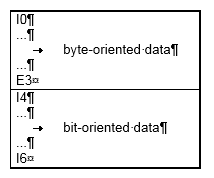
Area for byte-oriented data, analog inputs
Relative byte address | Bit position | Process image in the controller | Position in the block |
|---|---|---|---|
0, 1 | none | I0, I1 | POS10 |
2, 3 | none | I2, I3 | POS10 |
4, 5 | none | I4, I5 | POS13 |
6, 7 | none | E6, E7 | POS13 |
Area for bit-oriented data, digital inputs
Relative byte address | Bit position | Process image in the controller | Position in the block |
|---|---|---|---|
4 | 0 | E4 | POS01 |
4 | 1 | E4 | POS1 |
4 | 2 | E4 | POS2 |
4 | 3 | E4 | POS2 |
4 | 4 | E4 | POS3 |
4 | 5 | E4 | POS3 |
4 | 6 | E4 | POS4 |
4 | 7 | E4 | POS4 |
5 | 0 | E5 | POS5 |
5 | 1 | E5 | POS5 |
5 | 2 | E5 | POS6 |
5 | 3 | E5 | POS6 |
5 | 4 | E5 | POS15 |
5 | 5 | E5 | POS15 |
5 | 6 | E5 | POS16 |
5 | 7 | E5 | POS16 |
6 | 0 | I6 | POS17 |
6 | 1 | I6 | POS17 |
Positions POS14 and POS21 are not relevant to data exchange. They do not appear in the list. If a byte is not fully utilized, e.g. E8, the Bus Coupler pads the remaining bits of the byte with zeros.
Distribution of the process image in the Bus Coupler
The base addresses I0 and O0 listed here are used as relative addresses or addresses in the Bus Coupler. Depending on the higher-level DeviceNet system, the addresses can appear at a freely selectable position in the process image of the controller by the bus master. You can use the configuration software of the master to assign the bytes to the addresses in the process image of the controller.