Peripheral Data in the Process Image
After being switched on, the Bus Coupler determines the configuration of the inserted input/output terminals. The assignment of the physical slots for the input/output channels and the addresses in the process image is carried out automatically by the Bus Coupler.
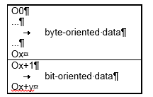
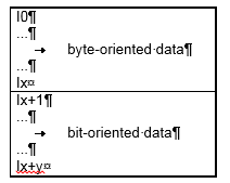
The Bus Coupler creates an internal assignment list, in which the input/output channels have a specific position in the process image. A distinction is made here according to inputs and outputs, and according to bit-oriented (digital) and byte-oriented (analog or complex) signal processing.
Two groups are created, one for inputs and the other for outputs. Each group has the byte-oriented channels in ascending sequence starting from the lowest address. The bit-oriented channels are placed after this block.
Digital signals (bit-oriented)
The digital signals are bit-oriented. This means that one bit in the process image is assigned to each channel. The Bus Coupler creates a memory area containing the current input bits, and ensures that the bits in a second memory area dedicated to the output channels are written out immediately.
The details of the assignment of the input and output channels to the controller's process image is explained fully with the aid of an example in the appendix.
Analog signals (byte-oriented)
The processing of analog signals is always byte-oriented. Analog input and output values are represented in memory by two bytes each. The values are represented in "SIGNED INTEGER" or "two's complement". The numerical value "0" stands for input/output value "0 V", "0 mA" or "4 mA". The maximum value of an output or input value is represented, according to the standard settings, by "7FFF" hex. Negative input/output values, e.g. -10 V are mapped as "1000" hex. The intermediate values are correspondingly proportional. A range with a resolution of 15 bits is not achieved for all input and output stages. With an actual resolution of 12 bits, the last 3 bits for outputs have no effect and for inputs they are read "0". Each channel also has a control and status byte. The control and status byte is the highest value byte. Version 2.0 of the DeviceNet coupler does not permit the control and status byte to be read. An analog channel is represented in the process image by 2 bytes. The following versions permit expansion of a channel's data width by means of the KS2000 configuration software.
Special signals and interfaces
A Bus Coupler supports Bus Terminals with other interfaces such as RS232, RS485, incremental encoder and others. These signals can be considered similarly to the analog signals named above. For some special signals the bit width of 16 is not sufficient. The Bus Coupler can support any byte width.
Default assignment of inputs/outputs to the process image
Once it has been switched on, the Bus Coupler finds out how many Bus Terminals are inserted, and creates an assignment list. The analog and digital channels, divided into inputs and outputs, are assembled into separate parts of this list. The assignment starts on the left next to the Bus Coupler. The software in the Bus Coupler collects the individual entries for each of the channels in order to create the assignment list counting from left to right.
Four groups are distinguished in the assignment
| Functional type of the channel | Assignment level |
|---|---|---|
1. | Analog outputs | assignment by bytes |
2. | Digital outputs | assignment by bits |
3. | Analog inputs | assignment by bytes |
4. | Digital inputs | assignment by bits |
Complex multi-byte signal Bus Terminals are represented as analog inputs or outputs.
The distribution of the process image in the Bus Coupler in overview:
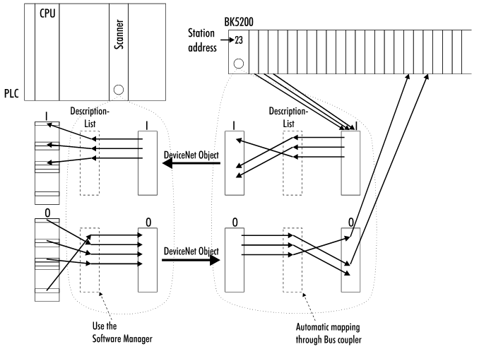
Process image in the BK5200 and in the PLC (scanner)
Data consistency
Data whose content is all correctly associated is said to be consistent.
Examples of data items that belong together are
- the high and low byte of an analog value (word consistency)
- the control/status byte and the associated parameter word for access to the registers.
Data consistency in the interaction of peripheral devices and their controllers is, in a basic sense, only assured for a single byte. In other words, the bits of a byte are written or read together. Byte consistency is sufficient for handling digital signals. Whenever values have a length of more than 8 bits, analog values for instance, the consistency must be extended. The different bus systems guarantee consistency up to the required length. Correct transfer of the consistent data from the bus system master to the controller is important. The corresponding manual for the bus system will provide a detailed description of the correct procedure, in particular the description of the master interfaces used. Those chapters of this manual that deal with the fieldbus refer to the most widespread interfaces.
Complex signal processing
All the byte-oriented signal channels such as RS232, RS485 or incremental encoders operate to some extent with byte lengths of more than two. Apart from the difference in length, they are always handled similarly to the analog signals.