LEDs
Overview
The Bus Coupler has two groups of LEDs for the display of status. The upper group (BK51x0) or left hand group (LC5100) indicates the state of the fieldbus.
On the upper right hand side of the BK51x0 bus coupler are two more green LEDs that indicate the supply voltage. The left hand LED indicates the presence of the 24 V supply for the Bus Coupler. The right hand LED indicates the presence of the supply to the power contacts. The two K-Bus LEDs (I/O RUN, I/O ERR) are located under the fieldbus LEDs. These indicate the operational state of the Bus Terminals and the connection to these Bus Terminals.
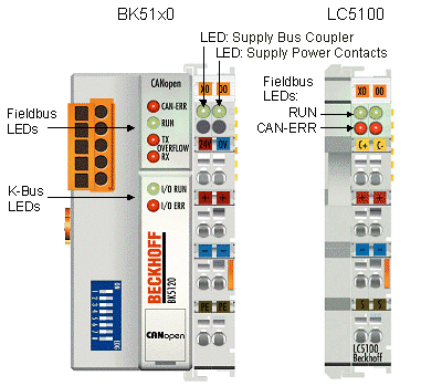
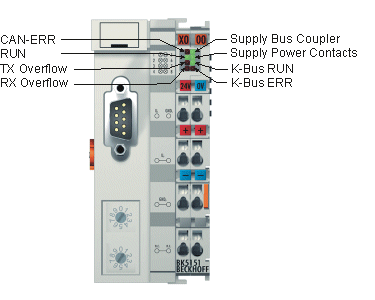
Fieldbus LEDs
The upper four LEDs (or the two LEDs on the left) indicate the operating state of the CANopen communication. The CAN-ERR LED here provides an indication of the physical state of the bus as well as of protocol errors. The RUN LED indicates the CANopen status of the bus node. The overflow LEDs come on in the event of a send or receive buffer overflow.
The behavior of the LEDs accords with CANopen recommendation DRP303-3 from CAN in Automation.
CAN-ERR blink code
CAN ERR | Meaning |
|---|---|
off | CAN bus has no errors |
fast flashing (approx. 50 ms on, approx. 50 ms off; alternating with RUN LED) | Automatic baud rate detection has not yet found a valid baud rate. Not enough telegrams on the bus yet. |
1 x blinking | CAN warning limit exceeded. There are too many error frames on the bus. Please check the wiring (e.g. termination resistors, screens, conductor length, stubs). Other possible causes for exceeding the warning limit: there are no other participating devices in the network (occurs, for instance, when the first node is started). |
2 x blinking | The guarding or heartbeat monitor has asserted, because either guarding telegrams or heartbeat telegrams are no longer being received. |
3 x blinking | A synchronization error has occurred. No sync telegrams were received from the Bus Coupler during the set monitoring time (object 0x1006 x 1.5). The bus node is pre-operational (PDOs switched off), and the outputs are in the error state. |
4 x blinking | Event timer error: The Bus Coupler has not received an RxPDO within the set event time (0x1400ff sub-index 5). The bus node is pre-operational (PDOs switched off), and the outputs are in the error state. |
on | CAN communication ceased due to serious CAN errors (bus off). Coupler must be restarted. |
RUN blink code
RUN | Meaning |
|---|---|
off | Firmware status < C0: Bus node is in stopped state. No communication is possible with SDO or PDO. |
fast flashing (approx. 50 ms on, approx. 50 ms off; alternating with CAN ERR LED) | Automatic baud rate detection has not yet found a valid baud rate. Not enough telegrams on the bus yet. |
1 x flashing (approx. 200 ms on, 1 s off) | Bus node is in stopped state. No communication is possible with SDO or PDO. |
alternating flashing (approx. 200 ms on, 200 ms off) | Bus node is in state pre-operational. The node was not yet started. |
on | Bus node is in Operational state. |
Tx overflow blink code
Tx Overflow | Meaning |
|---|---|
on | A transmit queue overflow has occurred. The bus coupler could not send its messages. Cause: e.g. excessive bus load. |
Blinking cyclically | Logical Tx queue overflow: SYNC interval too short. The coupler could not deliver all the TxPDOs before the following SYNC telegram. The TxPDOs are then, for instance, delivered in every second SYNC interval. Notice: The logical Tx queue overflow is signaled for approx. 10 sec and then reset. If it keeps recurring, signaling is maintained. |
Rx overflow blink code
Rx Overflow | Meaning |
|---|---|
on | A receive queue overflow has occurred. The Bus Coupler loses messages. |
Blinking cyclically | A receive queue overflow has occurred. The Bus Coupler has lost messages, but the overflow condition is no longer current. |
K-bus LEDs (local errors)
Two LEDs, the K-bus LEDs, indicate the operational state of the Bus Terminals and the connection to these Bus Terminals. The green LED (I/O RUN) lights up in order to indicate fault-free operation. The red LED (I/O ERR) flashes with two different frequencies in order to indicate an error. The errors are displayed in the blink code in the following way:
Flashing Code
fast blinking | Start of the error code |
|---|---|
First slow sequence | Error code |
Second slow sequence | Error argument (error location) |
Error type
Error code | Error code argument | Description | Remedy |
|---|---|---|---|
Persistent, continuous flashing |
| general K-bus error | - Check terminal strip |
1 pulse | 0 | EEPROM checksum error | - Set manufacturer’s setting with the KS2000 software |
1 | Inline code buffer overflow | ||
2 | Unknown data type | ||
2 pulses | 0 | Programmed configuration incorrect table entry / Bus Coupler | - Check programmed configuration for correctness |
(n>0) | Incorrect table comparison (terminal n) | ||
3 pulses | 0 | K-bus command error | - No terminal connected; attach terminals. |
4 pulses | 0 | K-Bus data error, break behind Bus Terminal n | Check whether the n+1 terminal is correctly connected; replace if necessary. |
5 pulses | n | K-Bus error during register communication with Terminal | Replace terminal n. |
7 pulses | n | BK5110 or LC5110: unsupported terminal detected at location n | only use digital terminals or Bus Coupler BK5120 |
Error code | Error code argument | Description | Remedy |
|---|---|---|---|
9 pulses | 0 | Checksum error in program flash memory | - Set manufacturer’s setting with the KS2000 |
13 pulses | 0 | Runtime K-bus command error | - One of the terminals is defective; halve the number of terminals attached and check whether the error is still present with the remaining terminals. Repeat until the defective terminal is located. |
14 pulses | n | Terminal n has the wrong format | - Start the coupler again, and if the error occurs again then exchange the terminal |
15 pulses | n | Number of terminals is no longer correct | - Start the coupler again, and if the error occurs again after this, use the KS2000 software to set manufacturer’s settings |
16 pulses | n | Length of the K-bus data (bit length) is no longer correct. n = bit length after booting | - Start the coupler again, and if the error occurs again after this, use the KS2000 software to set manufacturer’s settings |
17 pulses | n | Number of terminals is no longer correct. n = number of terminals after booting | - Start the coupler again, and if the error occurs again after this, use the KS2000 software to set manufacturer’s settings |
18 pulses | n | The terminal description is no longer correct after reset (n=terminal number). | - Start the coupler again, and if the error occurs again after this, use the KS2000 software to set manufacturer’s settings |
Error location
The number of pulses indicates the position of the last Bus Terminal before the fault. Passive Bus Terminals, such as a power feed terminal, are not included in the count.