LEDs
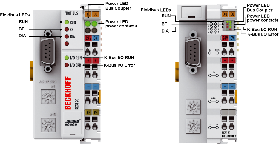
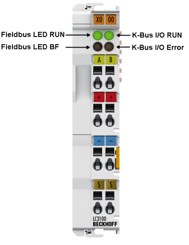
The Bus Coupler has two groups of LEDs for the display of status. The upper group (BK3xx0) or left hand group (LC3100) indicates the state of the fieldbus.
On the upper right hand side of the BK3xx0 Bus Coupler are two more green LEDs that indicate the supply voltage. The left hand LED indicates the presence of the 24 V supply for the Bus Coupler. The right hand LED indicates the presence of the supply to the power contacts. The two K-Bus LEDs (I/O RUN, I/O ERR) are located under the fieldbus LEDs. These indicate the operational state of the Bus Terminals and the connection to these Bus Terminals.
Fieldbus LEDs
The upper three LEDs (or the two LEDs on the left) indicate the operating state of the PROFIBUS communication:
BK3xx0 | ||||
|---|---|---|---|---|
I/O RUN | BF | DIA | Meaning | Remedy |
on | off | off | Operating state: RUN, inputs are read and outputs are set | Everything is operating correctly |
on | on | off, blinking | 1. Bus activity, but slave is already parameterized | Start master |
|
|
| 2. Bus error with reaction to PROFIBUS error: a.) K-bus outputs become 0 or b.) K-bus outputs are retained | Check parameters, configuration (possible error in DP start-up) |
off | off | off | Data exchange with the master is not started | PLC start |
off | on | on | No bus activity | Start the master, check the bus cable |
off | on | off, blinking | Bus error with reaction to PROFIBUS error: K-bus cycle is stopped | Start master, check parameters, configuration (possible error in DP start-up) |
DIA-LED blink codes
If an error occurs in the paramétrisation or configuration during DP start-up, this is indicated both through the fieldbus LEDs and in the diagnostic data.
Flashing Code
fast blinking | Start of the error code |
|---|---|
First slow sequence | Error code |
Second slow sequence | Error argument (error location) |
LC3100 | ||||
|---|---|---|---|---|
I/O RUN | BF | RUN | Meaning | Remedy |
on | off | on | Operating state: RUN, inputs are read and outputs are set | Everything is operating correctly |
on | on, blinking | on | 1. Bus activity, but slave is already parameterized | Start master |
|
|
| 2. Bus error with reaction to PROFIBUS error: a.) K-bus outputs become 0 or b.) K-bus outputs are retained | Check parameters, configuration (possible error in DP start-up) |
off | off | on | Data exchange with the master is not started | PLC start |
off | on | off | No bus activity | Start the master, check the bus cable |
off | on, blinking | on | Bus error with reaction to PROFIBUS error: K-bus cycle is stopped | Start master, check parameters, configuration (possible error in DP start-up) |
K-bus LEDs (local errors)
Two LEDs, the K-bus LEDs, indicate the operational state of the Bus Terminals and the connection to these Bus Terminals. The green LED (I/O RUN) lights up in order to indicate fault-free operation. The red LED (I/O ERR) flashes with two different frequencies in order to indicate an error. The errors are displayed in the blink code in the following way:
Error type
Error code | Error code argument | Description | Remedy |
|---|---|---|---|
Persistent, continuous flashing | - | general K-bus error | Check the Bus Terminal strip |
1 pulse | 0 | EEPROM checksum error | Set manufacturer’s setting with the KS2000 software |
1 | Inline code buffer overflow | Connect fewer Bus Terminals; too many entries in the table for the programmed configuration | |
2 | Unknown data type | Software update required for the coupler | |
2 pulses | 0 | Programmed configuration incorrect | Check programmed configuration for correctness |
n>0 | Incorrect table entry Bus Coupler / incorrect table comparison (Bus Terminal n) | Correct table entry / Bus Coupler | |
3 pulses | 0 | K-bus command error | No Bus Terminal connected; attach Bus Terminals |
One of the Bus Terminals is defective; halve the number of Bus Terminals attached and check whether the error is still present with the remaining Bus Terminals. Repeat until the defective Bus Terminal is located. | |||
4 pulses | 0 | K-bus data error, break behind Bus Coupler n | Check whether the n+1 Bus Terminal is correctly connected; replace if necessary. |
5 pulses | n | K-bus error in register communication with Bus Terminal n | Replace Bus Terminal n |
7 pulses | n | BK3x10 or LC3100: unsupported Bus Terminal detected at location n | Only use digital (bit oriented) Bus Terminals, or use a BK3120 Bus Coupler |
Error code | Error code argument | Description | Remedy |
|---|---|---|---|
9 pulses | 0 | Checksum error in program flash memory | Set manufacturer's setting with the KS2000 |
13 pulses | 0 | Runtime K-bus command error | One of the Bus Terminals is defective; halve the number of Bus Terminals attached and check whether the error is still present with the remaining Bus Terminals. Repeat until the defective Bus Terminal is located. |
14 pulses | n | Bus Terminal n has the wrong format | Start the coupler again, and if the error occurs again then exchange the Bus Terminal |
15 pulses | n | Number of Bus Terminals is no longer correct | Start the coupler again, and if the error occurs again after this, use the KS2000 software to set manufacturer’s settings |
16 pulses | n | Length of the K-bus data (bit length) is no longer correct. n = bit length after booting | |
17 pulses | n | Number of Bus Terminals is no longer correct. | |
18 pulses | n | Bus Terminal identifier no longer correct after reset (n = Bus Terminal number). |
Error location
The number of pulses indicates the position of the last Bus Terminal before the fault. Passive Bus Terminals, such as a power feed terminal, are not included in the count.