BC9xx0 - First steps
Necessary components
- A BC9xx0
- KL1114
- KL2134
- KL9010
- A 24 VDC power supply unit plus cabling material
- An Ethernet cross cable for a 1:1 connection between PC and BC9020 or BC9050 (without switch)
- A "normal" Ethernet cable between PC and BC9120
Setting the DIP switches
Set DIP switch 1 to ON, leave all other DIP switches OFF. A fixed IP address is used. Restart the BC after setting the DIP switches.
BC9050 then has the IP address 172.16.21.1
BC9020 then has the IP address 172.16.22.1
BC9120 then has the IP address 172.16.23.1
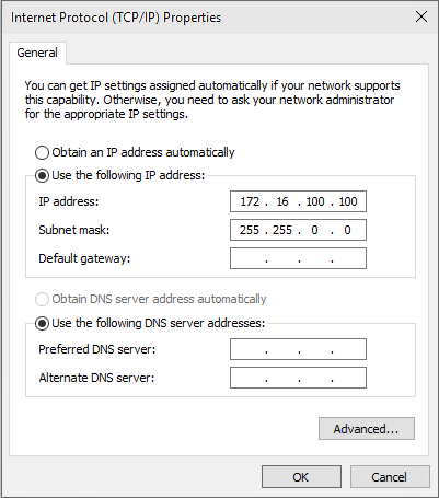
Set the IP address of your programming PC accordingly. For example: 172.16.100.100 (SubNetMask 255.255.0.0).
Use the >Ping< command to check whether TCP/IP communication is available. Open the prompt (DOS box) and enter the following, e.g. if a BC9050 is used: Ping 172.16.21.1. If the ping is successful you can continue. If the ping is not answered the communication is faulty. Check the Ethernet connection - right cable, the Controller DIP switch is switched on correctly, the IP address on the PC has changed.
Search BC via the System Manager
Start the System Manager. Select a new target system.
Click Search (Ethernet)...
Then click Broadcast Search. The BC now appears in the window. The host name is formed based on BC plus the last 3 bytes of the MAC ID and is therefore unique in your system. The MAC ID is printed on a label below the Bus Terminal Controller. Set the options button to IP Address and click Add Route. The Connected field should show a cross or "X". If a password query appears confirm with OK (leave blank). The password function is not implemented in the Bus Terminal Controller.
You can now select the Bus Terminal Controller. Click on the BC and confirm with OK.
Your BC with name and IP address is shown in red at bottom left in the System Manager. The field next to it should be blue and show Config Mode. If this is the case you can now scan the device. Right-click on IO Devices then Scan Devices.
The System Manager should find 2 devices. The Ethernet interface and the K-bus interface with the connected Bus Terminals.
Ethernet interface
Click on Upload to upload the current IP configuration.
PLC configuration
Append your PLC program here. First open the following example: (sample file) Save the file locally on your computer.
Recompile the file.
Re-save.
Change back to the System Manager and append your PLC program (right-click on PLC Configuration).
Search for your file (file type: tpy). Then open the tree. You will see all allocated data. Select the variables and link them to your Bus Terminals.
bIN_1 with KL1104 channel 1
bOUT_1 with KL2134 channel 1
bOUT_2 with KL2134 channel 2
bOUT_3 with KL2134 channel 3
After being linked you should now see the following.
Now activate the configuration in the System Manager. Click on  to download the configuration to the Bus Terminal Controller. Acknowledge all messages with OK. Finally you will be asked to restart the system. The BC will then reboot. The System Manager will lose the connection with the Bus Terminal Controller. Wait until the System Manager has re-established the connection. After a few seconds the status field in the bottom left corner of the System Manager should be green
  . If it is blue the BC has restarted in Config mode. Check your configuration.
Switch back to PLC Control. Go online and select the target system.
Log in and start the program.