BC9191 in Master /Slave mode
Requirements
- the basic application program is installed on the BC9191 (slave) and the default configuration is active
- an application that takes over the control and regulation algorithms of all connected BC9191 in master/slave mode is installed on the higher-level controller – in this example a CX5020 (master). A TwinCAT configuration is active on the master controller.
Basic information
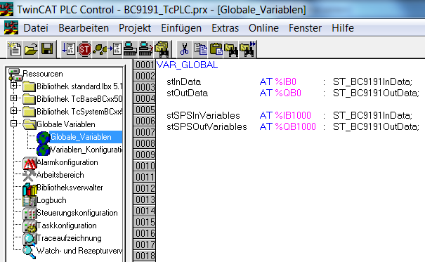
On delivery (default configuration) of the BC9191, the onboard I/Os have fixed addresses. The data for Ethernet communication start at the address offset 1000dec; this is a performance feature of the BC9191. This performance feature is used for the master/slave communication.
Inputs | Outputs |
|---|---|
Bus Terminal %IB0 ... | Bus Terminal %QB0 ... |
Ethernet DATA (PLC variables) %IB1000 ...(Modbus TCP/ADS-TCP/ADS-UDP) | Ethernet DATA (PLC variables) %QB1000 ...(Modbus TCP/ADS-TCP/ADS-UDP) |
... %IB2047 maximum | ... %QB2047 maximum |
Detailed description of the TwinCAT configuration of the master controller
- generate a new TSM file and save it under MasterSlave_TcSM.tsm
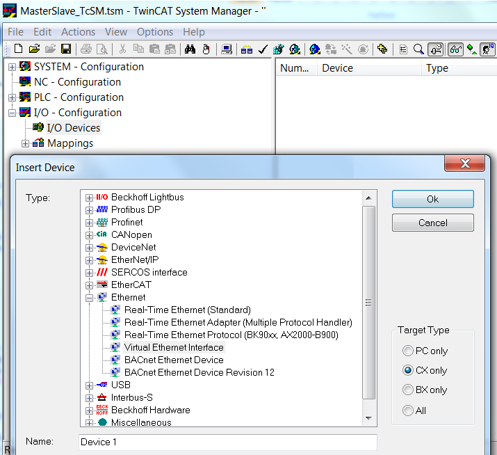
- Append Device ==> virtual Ethernet interface
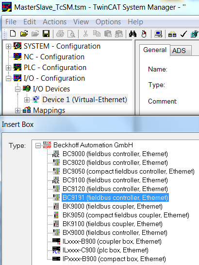
- Append Box ==> select BC9191 and confirm with OK /==> do not open a template, confirm with the Cancel button instead
- Add a PLC project so that the self-defined variable types are available.
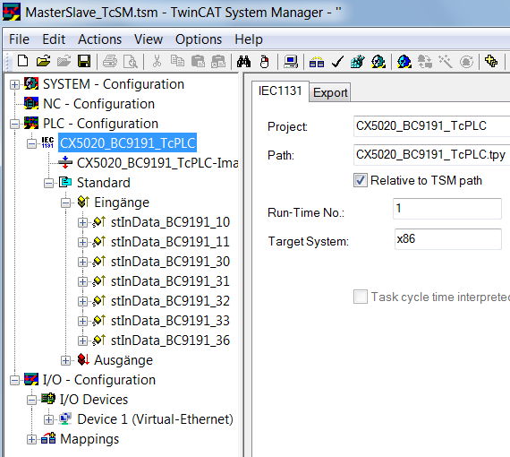
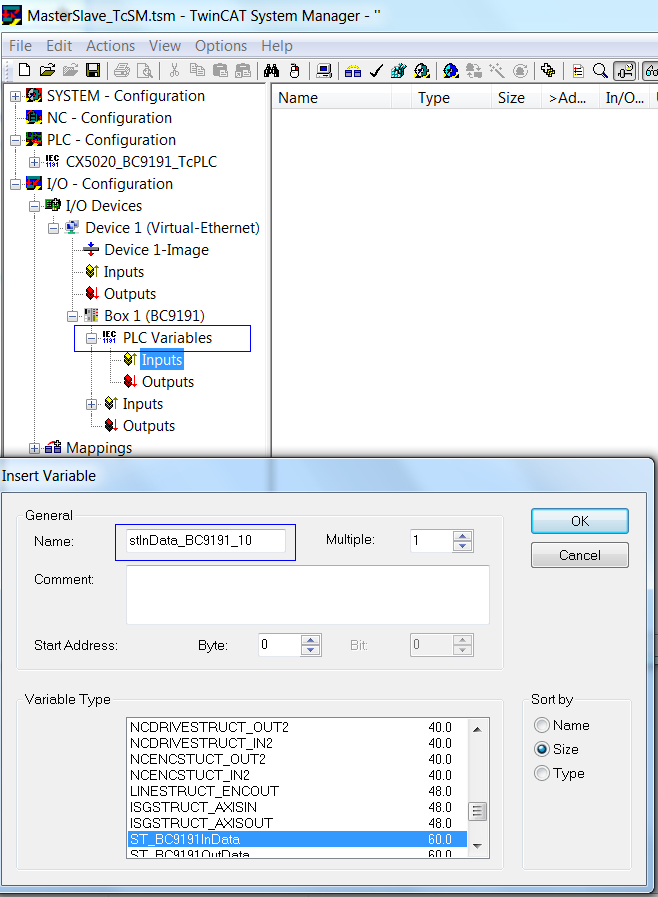
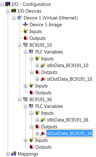
- insert PLC variables (for Ethernet communication) ==> inputs and outputs of the type ST_BC9191InData/ST_BC9191OutData under Box1 BC9191
- Edit a unique name, e.g. stInData_BC9191_10 and stOutData _BC9191_10 (reference to the name of the structure and to the BC9191 (e.g. 172.16.21.10))
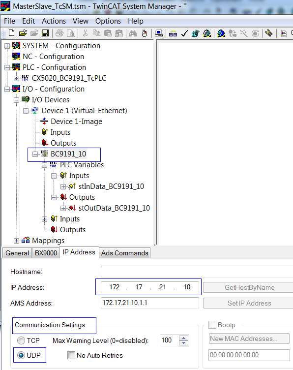
- Parameterization of Box 1 (BC9191)
- Declare a unique /assignable name e.g. BC9191_10
- Make communication settings in the IP address tab ==> adjust UDP and set the IP address
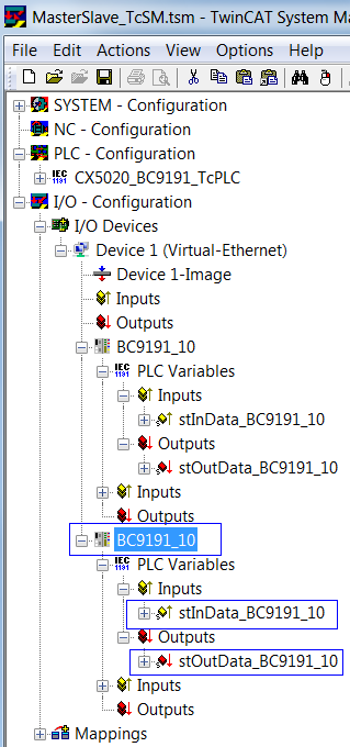
- If the parameterization of Box1 BC9191 is complete, it can be marked and copied as necessary.
- The respective name, the IP address and the names of the additional inputs and outputs must then be edited.
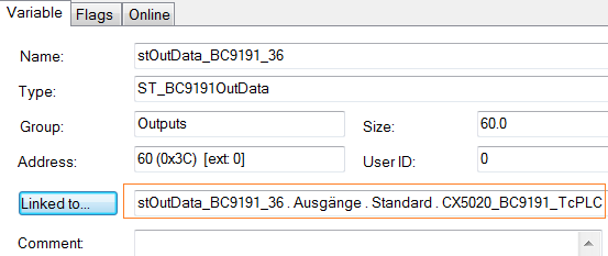
- Once the parameterization of the added BC9191s is complete, the inputs and outputs of the PLC task are linked to the inserted PLC variables
Detailed description of the TwinCAT PLC program of the master controller
 (CX5020_BC9191_TcPLC.pro as ZIP file) (sample file)
(MasterSlave_TcSM.tsm as ZIP file) (Sample file)
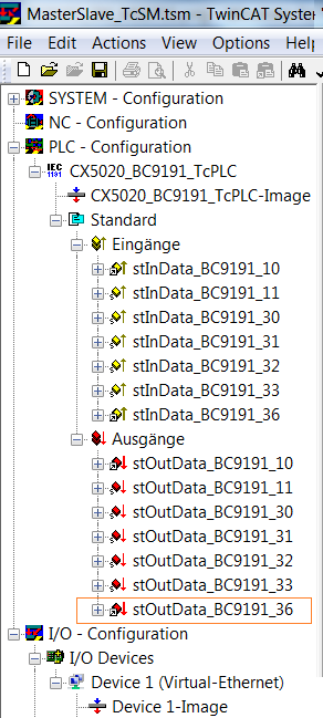
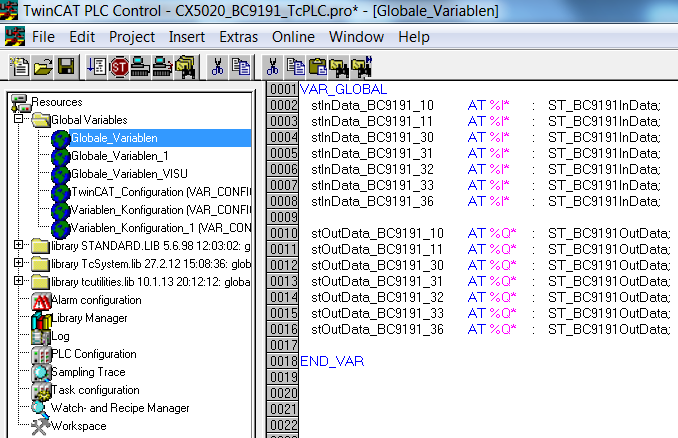
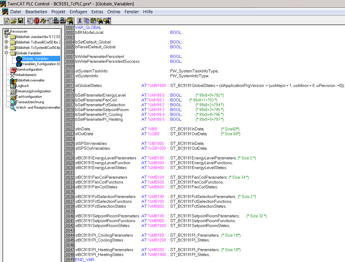
- Depending on how many BC9191s are integrated in the master/slave application, it is necessary to declare stInData_BC9191 and stOutData_BC9191 several times globally as allocated variables
- For the Ethernet communication used in the master/slave communication it is necessary to declare the PLC variables on the BC9191 side from the address offset 1000dec
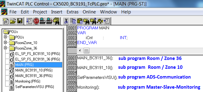
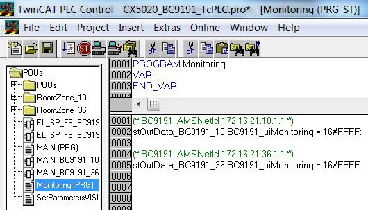
- The master/slave communication is monitored in the Monitoring () subprogram.
- If the connection between master and slave is interrupted, the value of the structure variable .BC9191_uiMonitoring falls to 0. In this case, the room/zone is no longer controlled centrally, but locally by the BC9191. The control functions are then taken over by the local PLC of the BC9191.
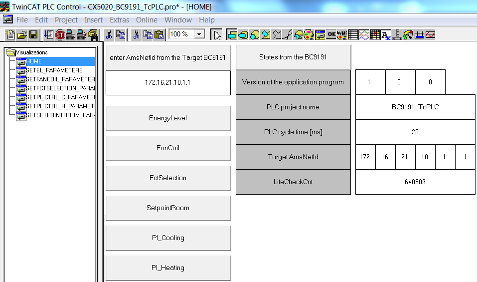
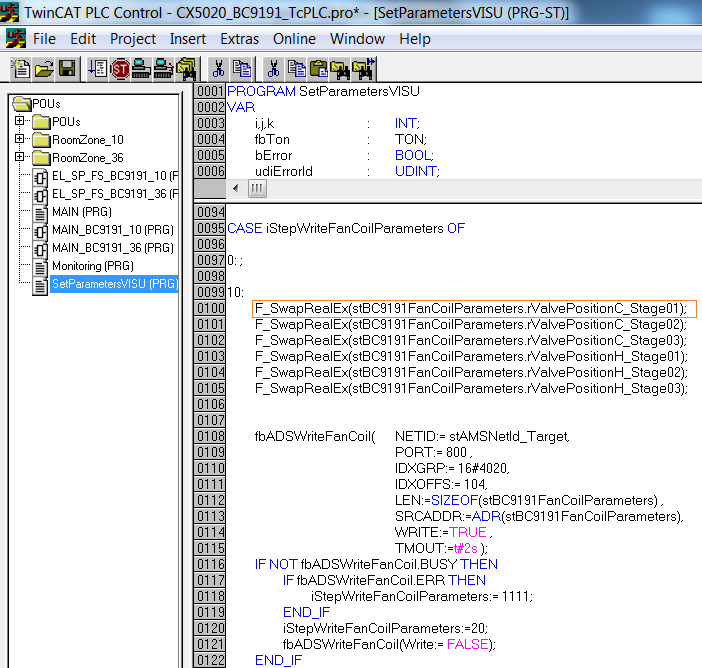
The master application contains a visualization. On the basis of the VISU and communication via Beckhoff ADS it is possible to execute read and write commands with the connected BC9191s
IndexGroup 16#4020 and 16#4021 ==> IndexOffset, see figure
NOTES
- The BC9191 (C165) and CX/PC (x86) have different memory alignments; this must be taken into account for data structures that are exchanged between the two control platforms. ==> See also the way the ST_BC9191InData and ST_BC9191OutData are structured.
BC (165) ==> Data structures have a WORD (2 bytes) memory alignment
PC / CX (x86) ==> Data structures have a BYTE (1 byte) memory alignment
CX (ARM) ==> Data structures have a DWORD (4 bytes) memory alignment - So that variables of the data type REAL are represented correctly by a PC on a BC9191 via the network by Beckhoff ADS, the variables of the data type REAL must be converted to the correct format. That also has to be done if the PC is accessed from the BC9191. The conversion, i.e. the swapping of the HI and LOW word of a REAL variable can be done on the BC9191 or on the PC side with the aid of the function F_SwapRealEx.
The PLC code, which runs locally on a BC9191 in the case of a communication interruption, is mapped once more on the master controller for each BC9191 and normally actively controls and regulates.
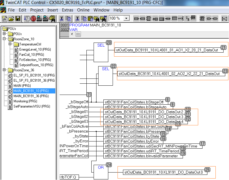
Blue and orange marked program sections belong functionally together.
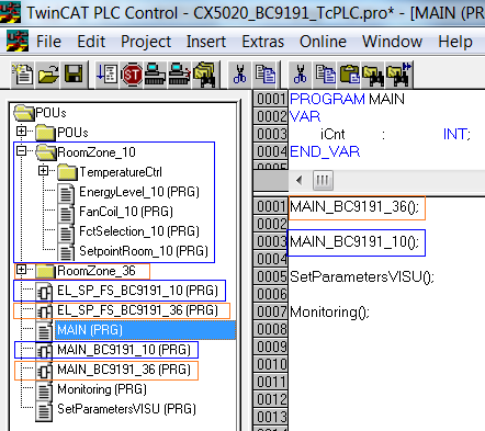
In the individual programs that refer to an explicit BC9191, the assignment of the physical inputs and outputs must be made in the corresponding structures and stInData_BC9191_xx stOutData_BC9191_xx .
Example for the BC9191_10
The assignment to the physical inputs takes place in the EL_SP_FS_BC9191_10(PRG) program section. (stInData_BC9191_10 : ST_BC9191InData;)
The assignment to the physical outputs takes place in the program part MAIN_BC9191_10(PRG). (stOutData_BC9191_10 : ST_BC9191OutData;)