Fan controller with room temperature control
The BC9191 is supplied with a pre-installed PLC program. This OLC program can be used for a three-stage fan controller with room temperature control (heating/cooling) for a 4-pipe system.
The factory-installed PLC code for TwinCAT 2 is also available for download as a sample program in a ZIP file (see Documentation and Downloads / Configuration files):
 BC9191: www.beckhoff.de/BC9191
BC9191-0100: www.beckhoff.de/BC9191-0100
Application
With the pre-installed standard air conditioning application it is possible to attain the highest energy efficiency standard of EN15232 Class A. The standard application contains the basic room air conditioning functions according to VDI 3813.
The application contains basic function blocks and basic functions such as:
- a local temperature measurement with smoothing function and a compensation value,
- a local setpoint value shift/setpoint correction
- a scaling function
- the control of analog actuators
- a PI controller with input via the proportional band
- occupancy detection and occupancy signal
- Window monitoring
- local overriding of the fan stages is possible
- load optimization is possible
Furthermore, room air conditioning functions are implemented, such as:
- energy level selection
- function selection
- Setpoint determination block for the different energy levels
- 3-stage fan control (FanCoil)
Notes
- The pre-installed standard air conditioning application is mapped as a default configuration, i.e. the TwinCAT System Manager is not required for the linking of the PLC variables with the I/O level.
- The Index Groups 16#4020 and 16#4021 can be accessed for both reading and writing from a higher-level controller, e.g. BMS or floor controller, by ADS or Modbus TCP. This is accounted for in the application.
- Parameters of individual subprograms are saved persistently. See also PersistentDataGlobalState.
Main_1 (main program)
All subprograms are called in the main program of the standard application. The connections and communication between the program blocks are given in the main program by the connecting lines. All the program blocks can therefore be seen in a single functioning context.
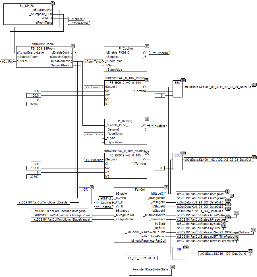
Connection from block 0 to block 1
The EnergyLevelSelection_SetpointGeneration_FunctionSelection subprogram (EL_SP_FS) transmits the information regarding the energy level, the setpoints of the four energy levels for the heating and cooling operation, the control function (heating/cooling/OFF) and the current room temperature (to blocks 2 and 4).
Connection from block 1 to block 2
FB_BC9191Room enables the cooling function with the valid/calculated energy level setpoint.
Connection from block 1 to block 4
FB_BC9191Room enables the heating function with the valid/calculated energy level setpoint.
Connection from block 1 to block 6
If the heating or cooling function is activated, it enables the fan coil on block 7.
Connection from block 2 to block 3
The cooling controller transmits its control value (0..100%) to the control valve. This control value is scaled to the output signal with the value range 0..32767; block 3.
Connection from block 4 to block 5
The heating controller transmits its control value (0..100%) to the control valve. This control value is scaled to the output signal with the value range 0..32767; block 5.
Block 7
3-stage fan coil, which switches the stages automatically depending on the control signal from the controller.
System diagram
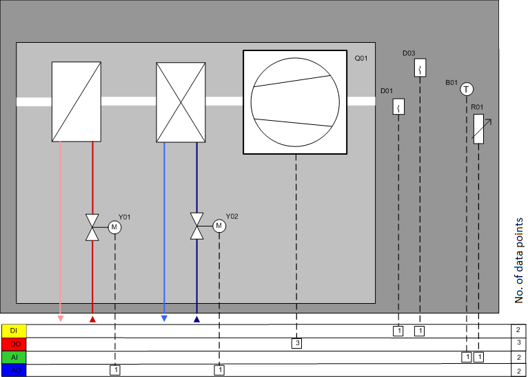
Data point list
DP | Name | Type | Program block / function block | Variable | Feature | Terminal strip |
|---|---|---|---|---|---|---|
Y01 | Heating valve | AA | PI_Heating / fbBC9191AO_0_10V_Heating | stOutData.KL4001_02_AO2_X2_22_21_DataOut | mandatory | X2 |
Y02 | Cooling valve | AA | PI_Cooling / fbBC9191AO_0_10V_Cooling | stOutData.KL4001_01_AO1_X2_20_21_DataOut | mandatory | X2 |
Q1 | 3-stage fan coil | DA | FanCoil | stOutData.KL9191_DO_DataOut.2 | binding | X3 |
D01 | Window contact | DE | EnergyLevel | stInData.KL9191_DI_DataIn.0 | mandatory | X1 |
D03 | Occupancy sensor | DE | EnergyLevel | stInData.KL9191_DI_DataIn.2 | mandatory | X1 |
B01 | Room temperature | AE | EL_SP_FS / fbBC9191TemperatureSensor | stInData.KL3201_AI_RTD_X1_8_9_DataIn | binding | X1 |
R01 | local set value generator | AE | EL_SP_FS / fbBC9191Poti / F_BC9191Scale | stInData.KL3061_01_AI_Poti_X1_10_9_DataIn | binding | X1 |
Key
AE: Analog input
AA: Analog output
DE: Digital input
DA: Digital output