Internal power supply, GND, potential groups, insulation test and PE
Internal power supply
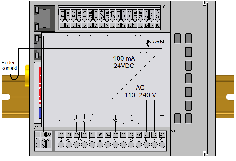
The BC9191 has an integrated wide-range power supply unit:
- The AC input voltage may be in the range of 110 VAC to 240 VAC.
- The integrated power supply unit generates all internally required voltages and also the electrically isolated voltage 24 VDC (pin X1/16).
- All GND connections are internally interconnected. To avoid interference, GND is capacitively connected to PE and the spring contacts for the mounting rail.
- The 24 VDC at pin X1/16, which is electrically isolated from the mains, can be loaded with max. 100 mA.
Potential groups
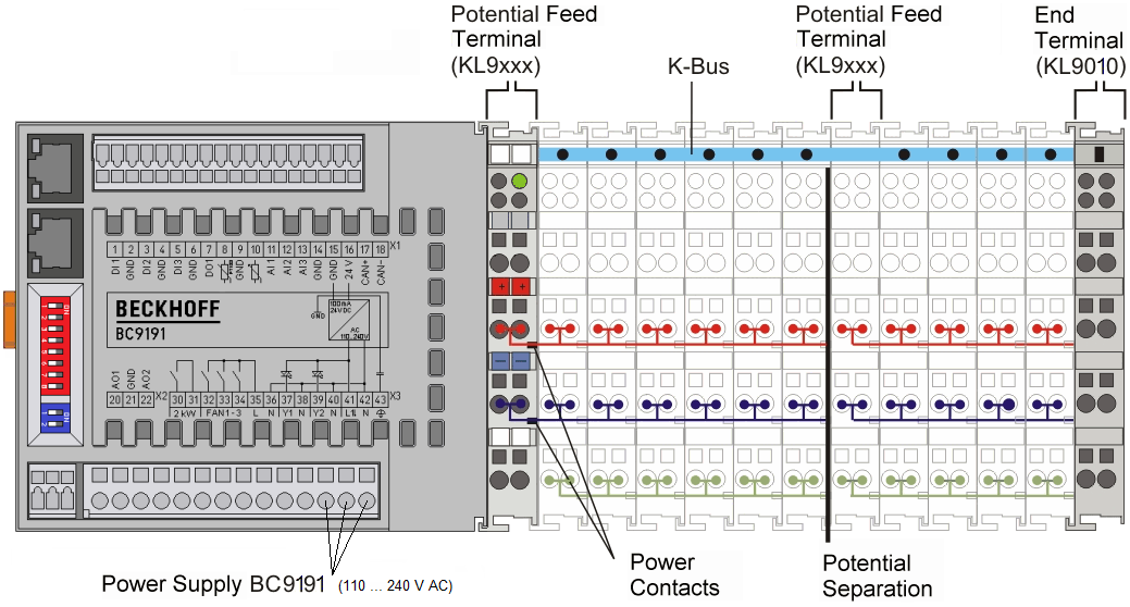
The BC9191 does not have power contacts. The power contacts of connected Bus Terminals must therefore be supplied by a power supply terminal. If an additional potential group is required, an additional power supply terminal must be provided, as in the example.
Power contacts
The connection between Bus Coupler / Bus Terminal Controller and Bus Terminals is realized automatically by latching the components. The transfer of the data and the supply voltage for the intelligent electronics in the Bus Terminals is performed by the K-bus. The supply of the field electronics is performed through the power contacts. Plugging together the power contacts creates a supply rail. Since some Bus Terminals (e.g. analog Bus Terminals or digital 4-channel Bus Terminals) do not loop through these power contacts or not completely, the pin assignments of the Bus Terminals must be observed.
The power supply terminals interrupt the power contacts, and represent the start of a new supply rail.
Insulation testing
The power contact labeled PE can be used as a protective earth. The contact is leading for safety reasons when mated and can dissipate short circuit currents up to 125 A.
It should be noted that, for reasons of electromagnetic compatibility, the PE contacts are capacitively coupled to the mounting rail. This can both lead to misleading results and to damaging the terminal during insulation testing (e.g. breakdown of the insulation from a 230 V power consuming device to the PE conductor). The PE supply line at the Bus Coupler / Bus Terminal Controller must be disconnected for an insulation test. In order to uncouple further supply locations for the purposes of testing, the power supply terminals can be pulled at least 10 mm out from the connected group of other terminals. In that case, the PE conductors do not have to be disconnected.
The PE power contact must not be used for other potentials.