Diagnostic LEDs
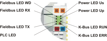
The Bus Coupler features status indicator LEDs. The row of LEDs on the left describes the status of the fieldbus and of the PLC. The row of LEDs on the right indicates the supply voltage and the K-Bus state.
LEDs for power supply diagnostics
|
LED (Power LEDs) | Meaning |
|---|---|
LED Us | LED off: No power supply (24 VDC) for electronics and K-Bus supply connected |
LED Up | LED off: No power supply 24 VDC connected at the power contacts |
LEDs for K-Bus diagnostics
|
LED (Power LEDs) | Meaning |
|---|---|
LED RUN | LED off: no K-Bus update, LED on, flashing: K-bus running |
LED ERR | LED off: no error, LED flashing: see K-Bus error code |
K-Bus error code diagnosis
|
Error | Error | Description | Remedy |
|---|---|---|---|
0 | - | EMC problems |
|
1 | 0 | EEPROM checksum error | Enter factory settings with the KS2000 configuration software |
1 | Code buffer overflow | Insert fewer Bus Terminals. Too many entries in the table for the programmed configuration | |
2 | Unknown data type | Software update required for the Bus Coupler | |
2 | - | Reserve | - |
3 | 0 | K-bus command error |
|
4 | 0 | K-bus data error, break behind the Bus Coupler | Check whether the n+1 Bus Terminal is correctly connected; replace if necessary. |
n | Break behind Bus Terminal n | Check whether the KL9010 Bus End Terminal is connected | |
5 | n | K-bus error in register communication with Bus Terminal n | Exchange the nth Bus Terminal |
6 | 0 | Error at initialization | Exchange Bus Coupler |
1 | Internal data error | Perform a hardware reset on the Bus Coupler (switch off and on again) | |
2 | DIP switch changed after a software reset | Perform a hardware reset on the Bus Coupler (switch off and on again) | |
7 | 0 | Note: cycle time was exceeded | Warning: the set cycle time was exceeded. This indication (flashing LEDs) can only be cleared by booting the Bus Coupler again. |
9 | 0 | Checksum error in Flash program | Re-transfer the program to the Bus Terminal Controller |
1 | Incorrect or faulty library implemented | Remove the faulty library | |
10 | n | Bus Terminal n is not consistent with the configuration that existed when the boot project was created | Check the nth Bus Terminal. The boot project must be deleted if the insertion of an nth Bus Terminal is intentional. |
14 | n | nth Bus Terminal has the wrong format | Start the Bus Coupler again, and if the error occurs again then exchange the Bus Terminal |
15 | n | Number of Bus Terminals is no longer correct | Start the Bus Coupler again. If the error occurs again, restore the manufacturers setting using the KS2000 configuration software |
16 | n | Length of the K-bus data is no longer correct | Start the Bus Coupler again. If the error occurs again, restore the manufacturers setting using the KS2000 configuration software |
LED bus - fieldbus diagnostics
|
LED | Meaning |
|---|---|
LED WD | not implemented |
LED RX | Flashes when data are being received |
LED TX | Flashes when data are being sent |
LED PLC - PLC diagnostics
|
LED | Meaning |
|---|---|
PLC LED | LED on: PLC running, |