Automatic PDO Mapping
BK51x0, IL23x0-B510
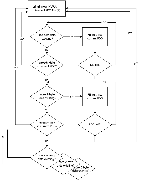
PDO1 and PDO2 are occupied, as described, with digital and analog process data. For each further PDO the CANopen node uses the procedure shown in the flow diagram below and assigns process data to the PDOs in the following order:
- Digital I/Os (if more than 64 are present)
- 1-bytes special terminals
- Analog I/Os
- 2-bytes special terminals
- 3-bytes special terminals
… - 10. 8-bytes special terminals
Data types are not mixed! A new PDO is taken for each new data type (sample see below).
Sample
A BK5120 (CANopen Coupler) has:
- 78 digital inputs and 48 digital outputs
- 6 analog inputs and 4 analog outputs
- a KL5001 (SSI encoder interface: 4 byte inputs by default)
- a KL6001 (serial interface: 4 byte inputs and 4 byte outputs by default)
- a KL5111 (incremental encoder interface) (6-byte inputs and 6-byte outputs)
- a KL6201 AS-i master terminal with default setting (22-byte process data interface)
PDO | Data content | Object | PDO | Data content | Object |
|---|---|---|---|---|---|
RxPDO1 | 5-byte digital outputs 1...48 | 0x6200, | TxPDO1 | 8-byte digital inputs 1...64 | 0x6000, |
RxPDO2 | 8-byte analog outputs 1..4 | 0x6411, | TxPDO2 | 4-byte analog inputs 1...4 | 0x6401, |
RxPDO3 | 4-byte serial interface | 0x2900, | TxPDO3 | 2-byte digital inputs 65...78 | 0x6000, |
RxPDO4 | 6-byte encoder outputs | 0x2D00, | TxPDO4 | analog inputs 5 and 6 | 0x6401, |
RxPDO5 | 8-byte ASI master 1: parameter data block | 0x3100, | TxPDO5 | 8 bytes: 4-byte SSI and 4-byte serial interface | 0x2800, |
RxPDO6 | 8-byte ASI master 1: Process data block outputs ASI slave 1...15 | 0x3100, | TxPDO6 | 6 bytes encoder input | 0x2C00, |
RxPDO7 | 8-byte ASI master 1: Process data block outputs ASI slave 16...31 | 0x3100, | TxPDO7 | 8-byte ASI master 1: parameter data block | 0x3000, |
|
|
| TxPDO8 | 8-byte ASI master 1: Process data block inputs ASI slave 1...15 | 0x3000, |
|
|
| TxPDO9 | 8-byte ASI master 1: Process data block inputs ASI slave 16...31 | 0x3000, |