EtherCAT as drive bus
EtherCAT technology overcomes these inherent limitations of other Ethernet solutions: the Ethernet packet is no longer received, then interpreted and copied as process data at every connection. The EtherCAT devices read the data addressed to them while the telegram passes through the device. Similarly, input data are inserted while the telegram passes through. The telegrams are only delayed by a few nanoseconds. Since an Ethernet frame reaches the data of many devices both in send and receive direction, the usable data rate increases to over 90%. The full-duplex features of 100BaseTx are fully utilised, so that effective data rates of > 100 Mbit/s (>90% of 2 x 100 Mbit/s) can be achieved.
The option of being able to use EtherCAT both for drive applications and for fast I/O signals was one of its main development aims right from the start. In existing systems, short cycle times and high synchronicity (as required for control loops that are closed via the bus) could only be realised with special drive buses. The SERCOS profile for servo drives according to IEC61491 was implemented in order to make the drive functionality compatible with existing standards and facilitate commissioning and optimised operation of the AX5000 through the user.
Special drive technology requirements
- Cycle time
- Synchronicity
- Simultaneity
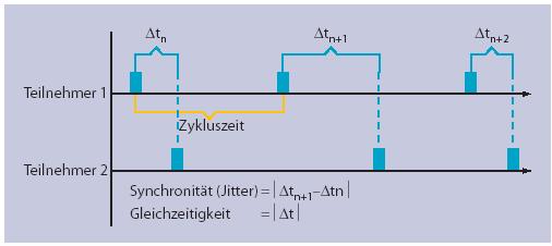
Typical values for the necessary cycle times lie between 1 and 4 milliseconds when position is specified cyclically, with position control in the drive. One microsecond is often quoted as an adequate value for synchronicity in drive technology.
While synchronicity describes the temporal jitter during processing of the functions in the device involved (drives and controllers), simultaneity defines the measure of temporal offset of these functions. Synchronicity is important for the individual devices, so that their own subordinate control loops can synchronize with the cyclic signal with the required precision. Simultaneity moreover enables distributed devices to work on a common task with identical time base.
Distributed clocks - EtherCAT slave controller features
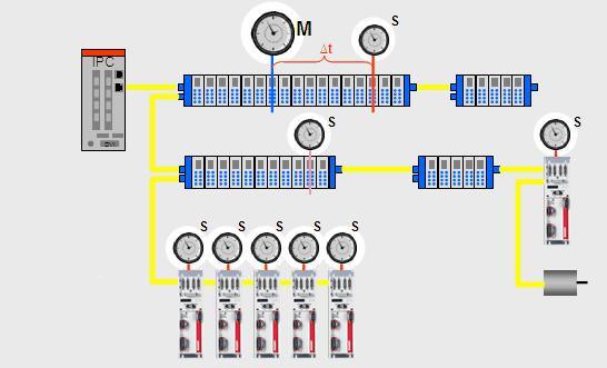
EtherCAT uses an approach based on distributed clocks for synchronization control: All devices have an independent clock as a basis for running local cycles and events. The crucial factor is that all clocks run at the same speed and have the same base time. A special control integrated in the EtherCAT Slave Controller (ESC) ensures that all clocks are guided by a reference clock and are synchronised irrespective of temperature and production tolerances.
Multi-protocol capability
Further important criteria for a fieldbus system that is to support drive technology are the communications protocol and profile used, which are responsible for compatibility and efficient data exchange between the controller and the drive. Instead of re-inventing the wheel, EtherCAT uses proven technology for this purpose.
None of the available protocols on their own support all communication requirements of modern fieldbuses (process data, parameter data, parallel TCP/IP, firmware updates, routing to subordinate bus systems, etc.). EtherCAT therefore introduces multi-protocol capability, consolidating the different protocols in a standardized mailbox. This enables quick and full conversion of existing devices to EtherCAT. The protocols relevant for drive technology are CANopen over EtherCAT (CoE) and Servo Profile over EtherCAT (SoE). They enable the advantages of EtherCAT in terms of transfer characteristics to be combined with proven, profile-specific drive functions. The Ethernet over EtherCAT (EoE) and File Access over EtherCAT (FoE) protocols provide options for integrating a web server in the drive, for example, or for efficiently exchanging firmware or cam plate tables via the bus.
Servo Profile over EtherCAT
The Servo Profile over EtherCAT (SoE) protocol enables the proven SERCOS device profile to be used, which is tailored for demanding drive technology and standardised in IEC 61491. The SERCOS service channel, and therefore access to all parameters and functions residing in the drive, is mapped to the EtherCAT mailbox. Here too, the focus is on compatibility with the existing protocol (access to value, attribute, name, units etc. of the SERCOS identifiers) and expandability about data length limitation. The process data (for SERCOS in the form of AT and MDT data) are transferred via the EtherCAT Slave Controller. The associated mapping is done SERCOS-compliant via the identifiers S- 0-0015, S-0-0016 and S-0-0024. For synchronisation - like for the CoE protocol - the synchronisation features of the EtherCAT Slave Controller are utilised as described above. This also includes - with associated quality improvements - those of standard SERCOS, so that implementation is correspondingly easy. The EtherCAT Slave State Machine explained above can also be mapped easily to the phases of the SERCOS protocol. "Pre-operational" corresponds to SERCOS, phase 2, and enables service channel communication without process data exchange. "Safe operational" is comparable with phase 3. Synchronisation is carried out as required, although for EtherCAT inputs that are already valid must be transferred. "Operational" exactly corresponds to phase 4 for normal, cyclic data exchange. As the name suggests, the EtherCAT Slave State Machine refers to a slave and - unlike SERCOS - therefore enables individual drives to be parameterised and started up independent of other devices.
Conclusions
While EtherCAT is not a pure drive bus, it meets the associated requirements at least one order of magnitude better than familiar, specialised systems. Drive, I/O and communication buses therefore no longer have to be separated. Even demanding tasks, such as measurement technology applications, can be integrated and enable new functionalities to be utilised with classic control technology. Because proven communication profiles are used, migration of existing devices and applications can easily be accomplished. For drive technology in particular, a small number of profiles have been developed and tried and tested over years. It also means that the complete tool chain and existing experience with the parameterisation of associated drives is maintained.
IDNs used
This is a example for the structure and description of an IDN. A list and description of all relevant IDNs can be found in the separate IDN description (chm).
S-0-0001, Control unit cycle time (TNcyc)
The control unit cycle time defines the cyclic intervals during which the control unit makes new command values available. The control unit cycle time shall be transferred from the master to the slave during CP2 and becomes active in the slave during CP3. The control unit cycle time should be an integer multiple of the communication cycle time. tNcyc = tScyc * n [n =1,2,3,4...]
Attributes: | |
|---|---|
Unit: | us |
Default value: | 500 |
Min value: | 62 |
Max value: | 20000 |
Data length: | 16 |
Format: | binary |
Cyclic transfer: | No |
Write protected: | SafeOp, Op |
Decimal point: | 0 |
Device parameter: | Yes |