General description of a homing procedure
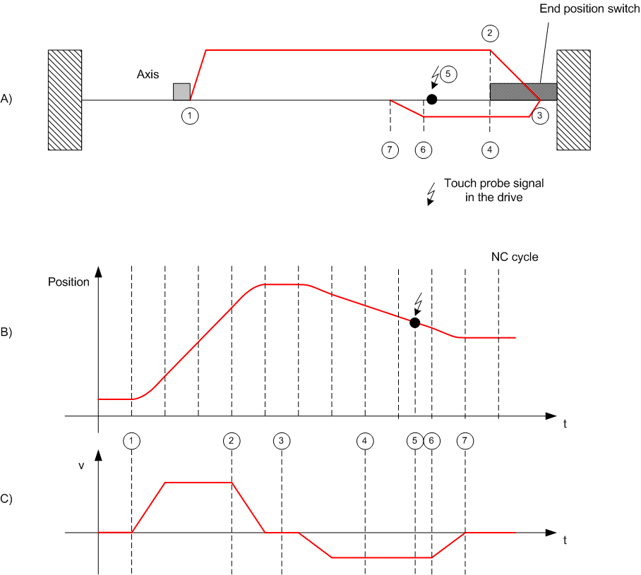
Figure A shows a schematic diagram of a homing procedure with individual velocity profile phases.
- When the machine is switched on the axis is in a random position (1).
- Homing is initiated, and the axis travels towards the reference cam.
- Once the reference cam is detected, the axis stops and reverses.
- The axis moves away from the reference cam and detects the falling edge of the reference cam signal.
- The axis continues and searches for a sync pulse or another distinctive event, depending on the reference mode setting. This step may be omitted where appropriate.
- The occasion is detected and the specified reference position is set.
- The axis stops and thus stands slightly away from the reference position. The reference position was set a short while before with maximum accuracy.
Figures B and C show the position and velocity profile during homing.