Mode parameterisation according to SoE
Parameterization according to IDN S-0-0032
Bit | Operation mode |
|---|---|
0 | no mode of operation |
1 | torque control |
2 | velocity control |
3 | position control feedback 1 |
4 | position control feedback 2 |
11 and 12 | position ctrl feedback 1 + 2 lag less |
32769 | torque control using dynamic MDT |
32770 | velocity control using dynamic MDT |
32771 and 32772 | position control feedback 1 + 2 using dynamic MDT |
32779 and 32780 | position control feedback 1 + 2 lag less using dynamic MDT |
Cascaded control structure
The following figure shows a cascade of current, speed and position controllers commonly used in control technology.

The control structure shown above makes it possible to achieve high dynamics and positioning accuracy. In such a cascade, the bandwidth of the individual control loops decreases from the inside to the outside. When starting up the cascade, always begin with the innermost circle (the current controller). This is then followed by the speed and position controller. In the case of Beckhoff motors the current controller is parameterized in the factory.
2 operation modes are suitable for positioning:
- Velocity setpoint specification (velocity interface):
Cyclic velocity setpoints are sent from the controller to the drive. The position controller is implemented on the controller side (NC). - Position setpoint specification (position interface):
Cyclic setpoint positions are sent from the controller to the drive. The position controller is implemented in the drive. Only the setpoint profile is calculated on the controller (NC). A high bandwidth in the position control is achieved here (no EtherCAT dead time in the closed control loop). This operation mode should always be used if the controller allows it.
Profile generator
The profile generator generates curve profiles from a positioning order of the MC_MoveAbsolute PLC function block. In each NC cycle, at a defined time (interpolation points T1 - Tn), the setpoints of this positioning order are transferred to the axis control. In order for the servo drive to move optimally, the setpoints of the profile generator must be triggered with the SAF tasks of the EtherCAT fieldbus. The SAF task ensures that the interpolation points (T1 – Tn) are transported to the servo drive.
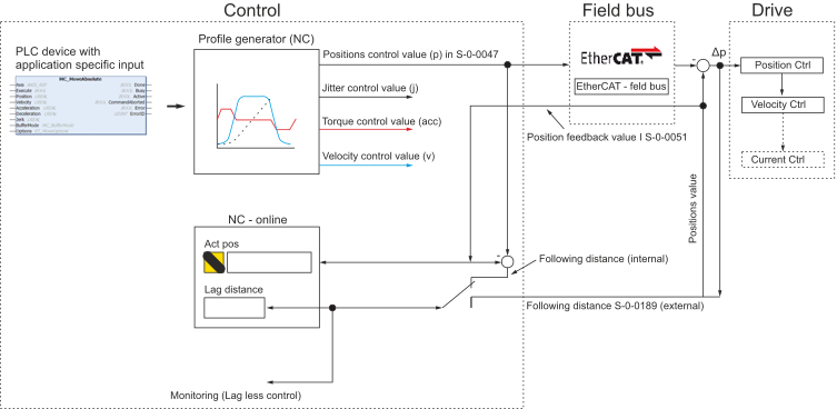
MC_MoveAbsolute is predominantly used for linear axis systems. Using the PLC function block, axes can be moved from the initial position to the target position at a velocity v.
 | Further information is available at: PLC--> Libs --> TwinCAT 3 PLC Lib: Tc2_MC2 --> Motion function blocks --> Point to Point Motion |
Position interface
The position calculated by the profile generator is transmitted to the drive via the EtherCAT fieldbus. As a result, the drive receives a new position setpoint in each SAF cycle. Due to the position controller in the drive (see cascaded control structure), the EtherCAT dead time in the position control loop is eliminated. The use of the position controller in the drive renders the position controller in the NC ineffective (parameterization in the TcDriveManager). The “Control Kp factor” in the NC-online window of the TcDriveManager thus has no effect.
The actual position of the feedback system is mapped to the NC. It is useful here to select the default lag error, which is calculated by the drive (automatically when reading a standard Sercos axis). This lag error supplies the real position difference. The lag error can also be calculated internally via the NC. However, this calculation includes the dead time of the fieldbus (EtherCAT) and is falsified as a result.
This operation mode is configured via parameter S-0-0032. In addition to the drive's internal position controller, velocity feedforward can be activated. If no feedforward control is used, the set value for the speed controller only consists of the product of the control deviation and the position controller gain.
Feedforward control is generally advisable. Depending on the application the weighting of this parameter can be set between 0 and 100%.
Velocity interface
If the servo drive has no position controller, or if the setpoint velocity has to be influenced by additional components, then the position controller can be relocated to the controller. The setpoint velocity calculated by the profile generator is supplemented by the value that the TwinCAT-PTP position controller calculates on the basis of a tracking error.
As for position specification, the interpolation points for the velocity setpoints have a temporal resolution that is greater than the interpolation cycle (task time of the SAF task of the NC).
This operation mode is configured via parameter S-0-0032.
S-0-0032 (main mode) | ||
|---|---|---|
0 0000 0010 | 0x02 | Velocity control |
A further mode is torque control. In this mode, the set torque is specified. The actual torque is returned as feedback. Torque control is handled by the drive. If the actual value is based on an external measuring point, regulation (setpoint generation) should be provided in the control system.
S-0-0032 (main mode) | ||
|---|---|---|
0 0000 0001 | 0x01 | Torque control |