X06: Digital I/Os
| |
Destruction of the AX5000! This connector is not designed for external power supply. It is supplied via the 24 V supply (periphery) of connector X03. |

| Terminal point | Signal | Output current | Wire cross-section |
|---|---|---|---|---|
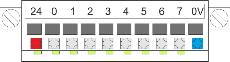
I/O connector without LEDs
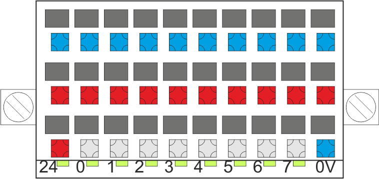
I/O connector with LEDs
ZS4500-2008 (optional)
| 24 | Power supply for the external sensors (switches/initiators) | max. 1 A | Max. 1.5mm² |
0 | Input 0 |
| ||
1 | Input 1 |
| ||
2 | Input 2 |
| ||
3 | Input 3 |
| ||
4 | Input 4 |
| ||
5 | Input 5 |
| ||
6 | Input 6 |
| ||
7 | Input 7 or output (configurable) | max. 0.5 A | ||
0 V | GND (-) |
|

Beckhoff servo drives of the AX5000 series have eight (0-7) digital inputs. The input 7 can be configured to an output. All inputs and outputs can be freely assigned to channel A or B. The information provided in parameter P-0-0801 shows the status of the digital inputs. These can be transferred to the cyclic interface and provided in the PLC / NC.
There are two different ways to configure input 7 as an output:
- A PLC output (P-0-0800) is assigned to parameter P-0-0802
- A bit is assigned to a drive function and set to the output as the result
Whether the signal source comes from the servo drive or the PLC is indicated by parameter P-0-0801.
Voltage level | State |
|---|---|
-3 V ... 5 V | 0 or "false" |
15 V ... 30 V | 0 or "false" |
 | Configuration of the connector signal inputs: The signal inputs can be configured with the following functions: P-0-0251, P-0-0400, P-0-0401, P-0-0402, P-0-0800, P-0-0801, P-0-0802. For further information please refer to the documentation for the |