Overview of sockets X41 (channel A) and X42 (channel B)
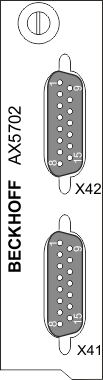
Pin | EnDat® 2.2 | BiSS® C | Max. output current |
|---|---|---|---|
1 | n.c. | n.c. | 0.25 A / channel |
2 | GND | GND | |
3 | n.c. | n.c. | |
4 | 5 V+ ±10% | 5 V+ ±10% | |
5 | Data+ | Data+ | |
6 | 12 V | 12 V | |
7 | n.c. | n.c. | |
8 | CLK+ | CLK+ | |
9 | n.c. | n.c. | |
10 | GND sense | GND sense | |
11 | n.c. | n.c. | |
12 | 5 V sense ± 10% | 5 V sense ± 10% | |
13 | Data- | Data- | |
14 | n.c. | n.c. | |
15 | CLK- | CLK- |
1)Attention: wire break detection is not supported for TTL encoders.
The digital inputs "A" to "D" can be connected either to X or to Y.
The digital inputs "E" and "F" must be connected to X (+) and X (-).