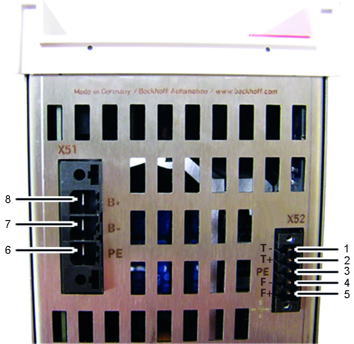
Pin strip assignment of X51 and X52
No. | Name |
|
|---|---|---|
1 | T- = input of the temperature measurement sensor of the external brake resistor |
|
2 | T+ = input of the temperature measurement sensor of the external brake resistor | |
3 | PE = protective conductor | |
4 | F- = output to the fan controller | |
5 | F+ = output to the fan controller | |
6 | PE = protective conductor | |
7 | B- = output to the controller of | |
8 | B+ = output to the controller of |
Please refer to the servo drive ‘Startup’ manual for the pin assignments of the remaining inputs and outputs.
 | Temperature rise in the external brake resistor The temperature rise of the external brake resistor should be monitored continuously via temperature contacts (1) and (2). |