Ext. brake resistor enabled (system / standard)
|
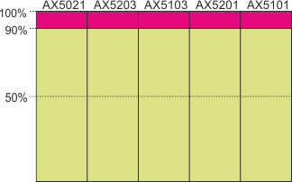
In this operation mode the capacity of the DC link of the brake module is reduced by approx. 10%. At 90% DC link load the brake chopper then directs the generated braking energy to the external brake resistor and, when this has reached its capacity limit, into the internal brake resistor. In this case the brake energy is first fed into the brake module, since the brake choppers in the other servo drives are only activated at 100% utilization of the DC link. This operation mode is set as the default, because no further configuration of the devices in the DC link system is necessary apart from the basic configuration of the brake module. If the external brake resistor of the brake module is mounted outside the control cabinet, then the thermal load in the control cabinet is also lower.
|
Ext. brake resistor enabled (standalone brake chopper)
|
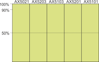
In this case the capacity of the DC links is fully utilized. This operation mode must be selected and, apart from the basic configuration of the brake module, the internal brake resistors of the devices in the DC link system should be deactivated, as otherwise the thermal load in the control cabinet will also increase. In order to reduce the thermal load further, it is a good idea to mount an external brake resistor on the brake module outside the control cabinet.
|