Configuration in the TCDriveManager
Integrating the brake module into the DriveManager and Power Management
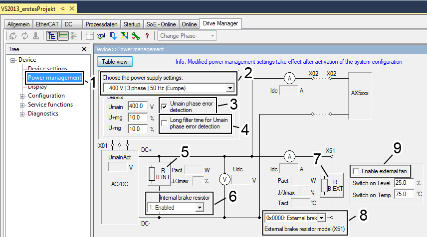
In the TwinCAT Drive Manager, the brake module can be integrated and configured as a normal digital input/output.
The position designations are described in the table below.
Pos. | Name |
| Pos. | Name |
|---|---|---|---|---|
1 | Power management |
| 6 | Activation / deactivation of the internal braking resistor |
2 | Mains voltage selection |
| 7 | External braking resistor parameter list |
3 | Phase monitoring (deactivate for single-phase mains) |
| 8 | 0 = Deactivate the external braking resistor |
4 | Delay time until the phase monitoring responds (activate if mains is unclean) |
| 9 | Activating / deactivating the fan of the external braking resistor and setting the switching thresholds Switch on Level: Percentage specification of the nominal power value of the external braking resistor Switch on Temp.: Specification of the max. temperature value of the external braking resistor in "°C". |
5 | Internal braking resistor parameter list |
|
|
|