Installation examples (60 A - 170 A devices)
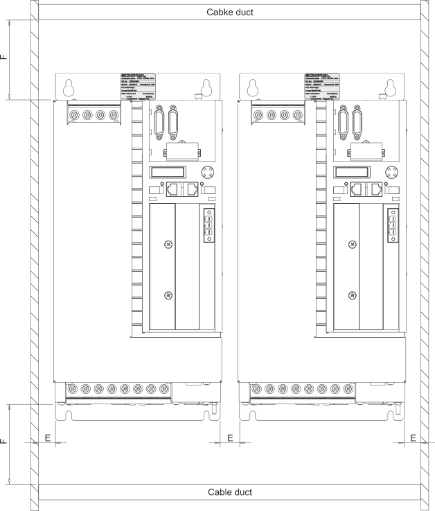
AX | F [mm] | E [mm] |
|---|---|---|
5160 and 5172 | ≥ 180 | 20 |
5190 and 5191 | ≥ 180 | 40 |
5192 and 5193 | ≥ 180 | 40 |
Installation in the control cabinet
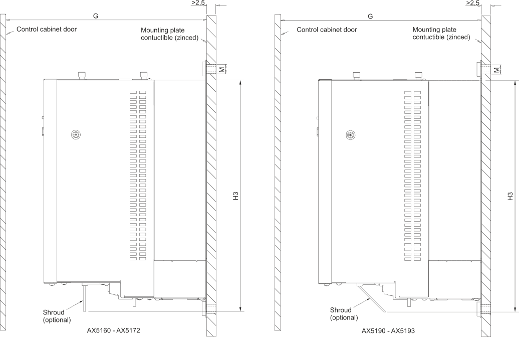
AX | G [mm] | M [mm] | H3 [mm] |
|---|---|---|---|
5160 and 5172 | ≥ 300 | 4 x M5 | 445 |
5190 and 5191 | ≥ 300 | 4 x M8 | 640 |
5192 and 5193 | ≥ 500 | 4 x M8 | 640 |
| |
Caution - Risk of injury through electric shock! The mounting plate must be grounded according to the statutory regulations. Non-compliant grounding of the AX5000 can cause EMC problems. |

Mounting of the shielding bracket (optional)
AX5160 and AX5172
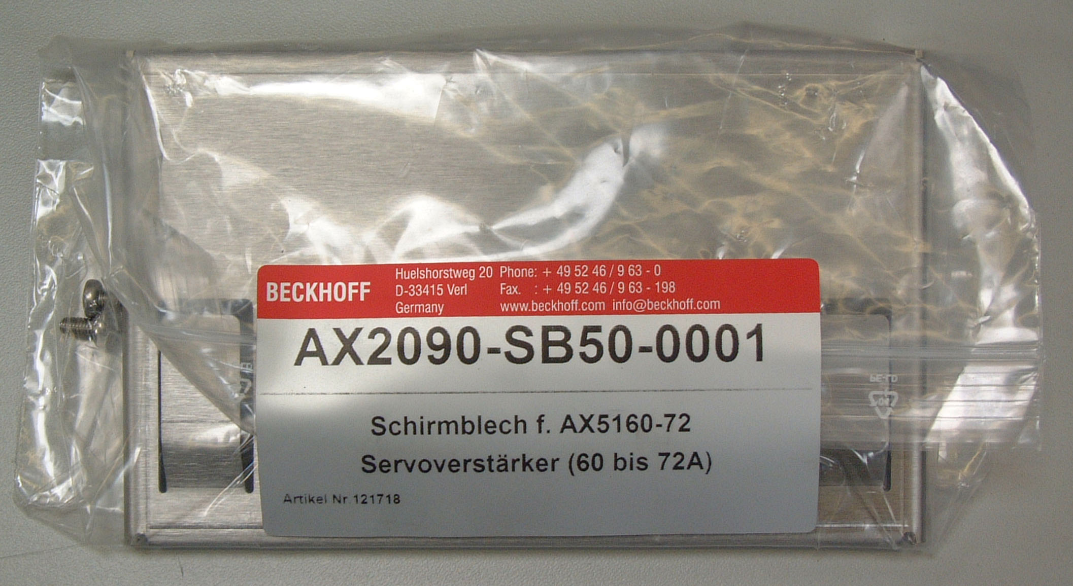
AX2090-SB50-0001:
Shielding bracket set for AX5160 and AX5172 consisting of shielding bracket and screws (2 M4 x 10).
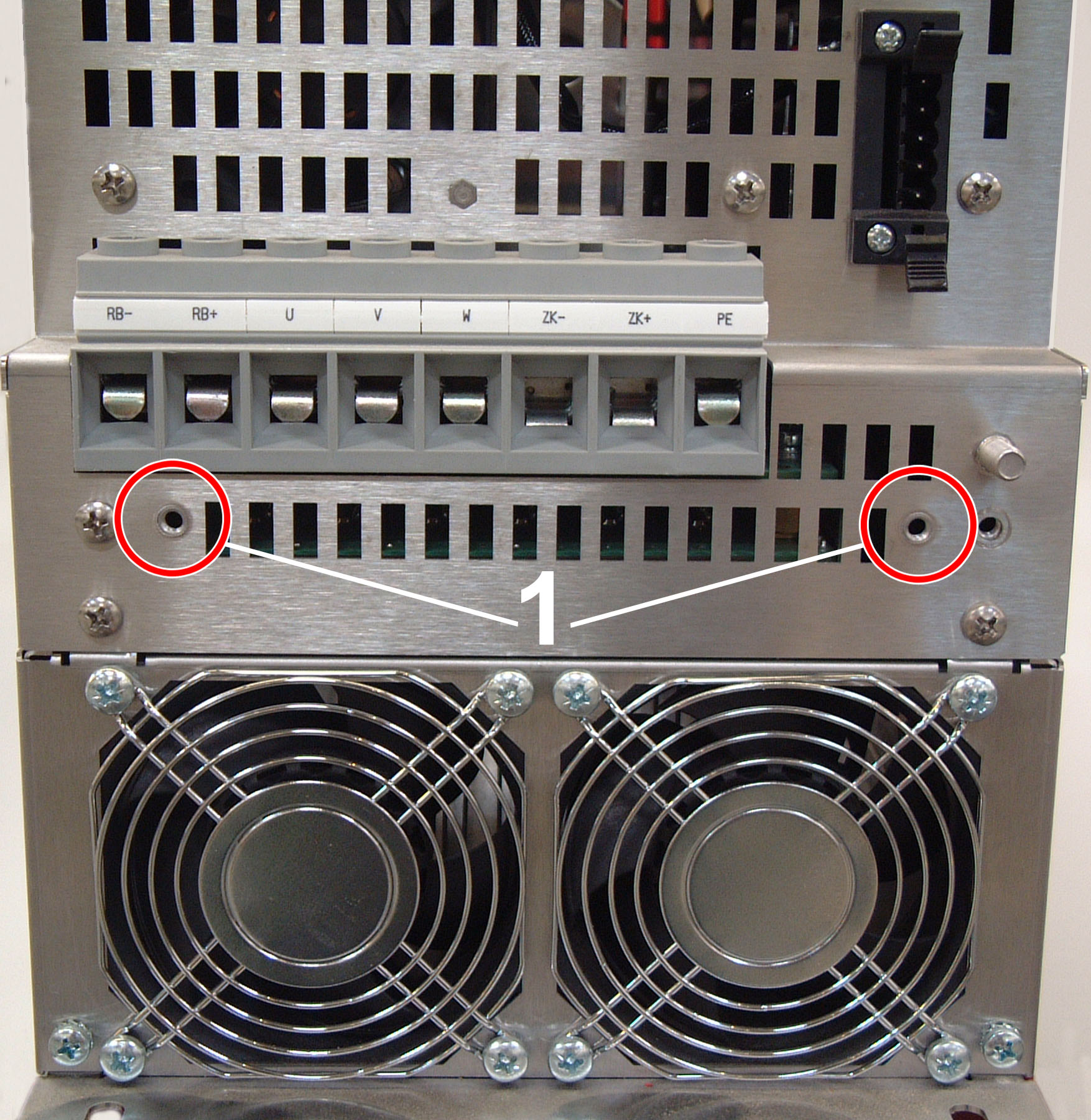
Preparation for installation:
1.) The threaded holes (1) for installing the shielding bracket are not fitted with screws when the AX5160 / AX5172 servo drive is delivered.
Before installing the shielding bracket, check that the threaded holes are free of dirt or similar.
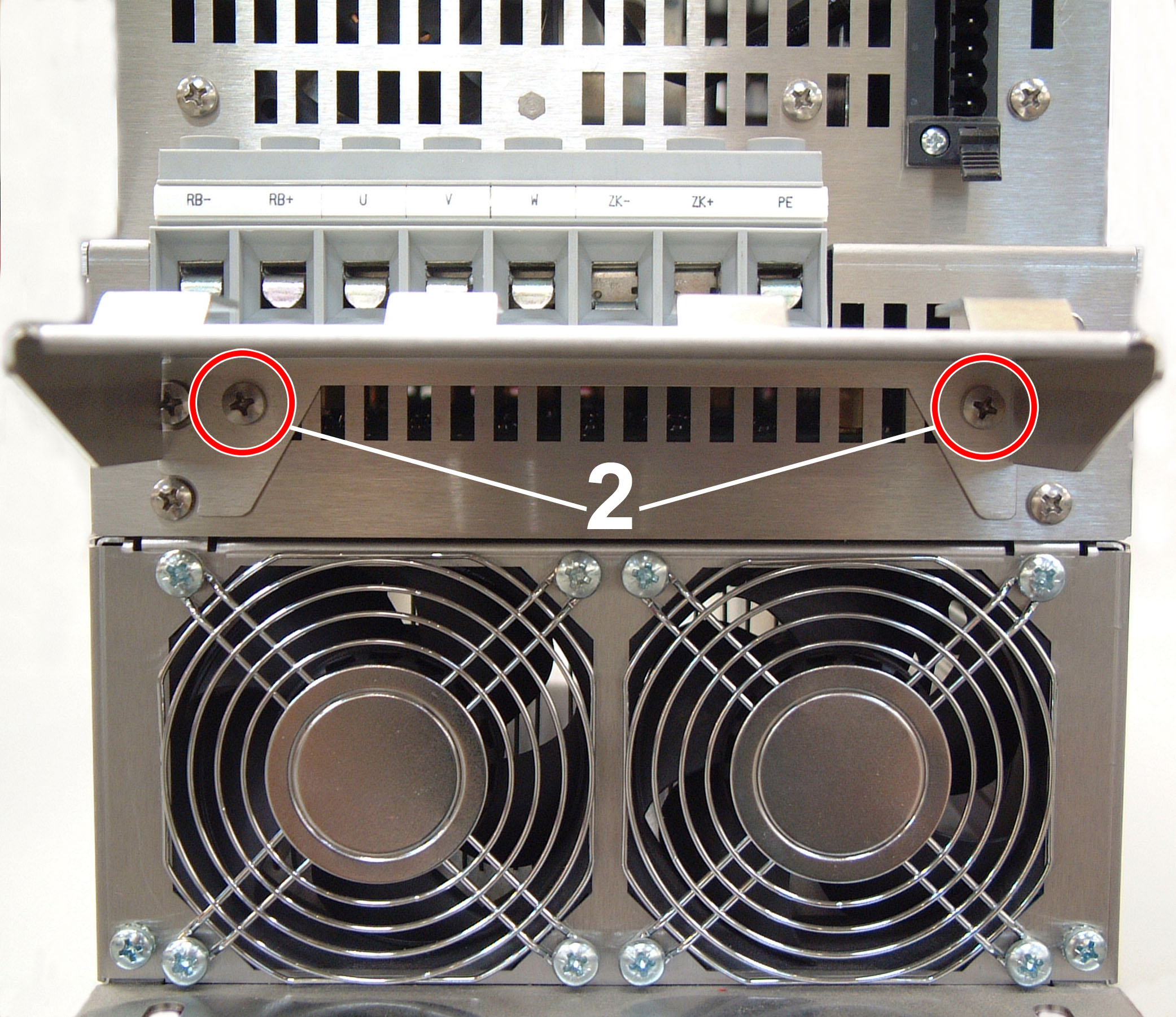
Shielding bracket installation:
2.) Position the shielding bracket.
3.) Fasten the shielding bracket with the screws (2). Only use the screws included in the scope of delivery of the shielding bracket set for installation.
4.) Connect the cables to the terminals provided. Attach the shield to the tabs.
AX5190 and AX5191
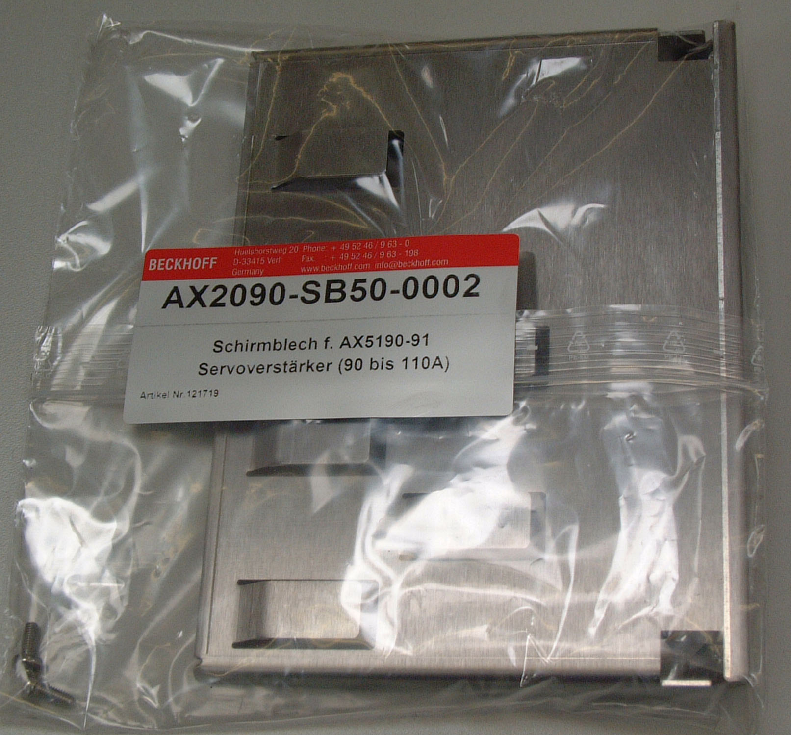
AX2090-SB50-0002:
Shielding bracket set for AX5190 and AX5191 consisting of shielding bracket and screws (2 M4 x 10).

Preparation for installation:
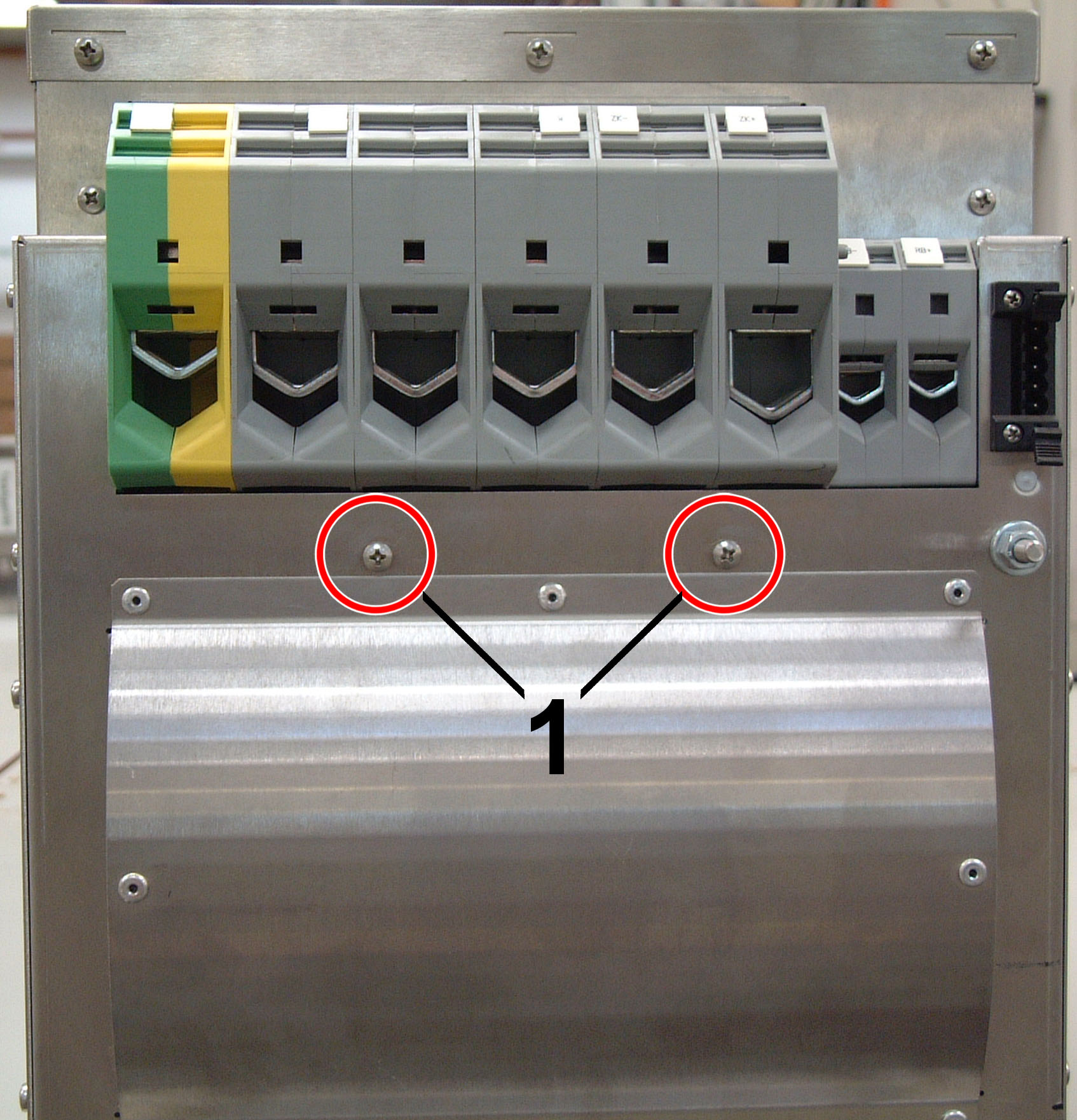
1.) Remove the 2 pre-assembled screws (1).
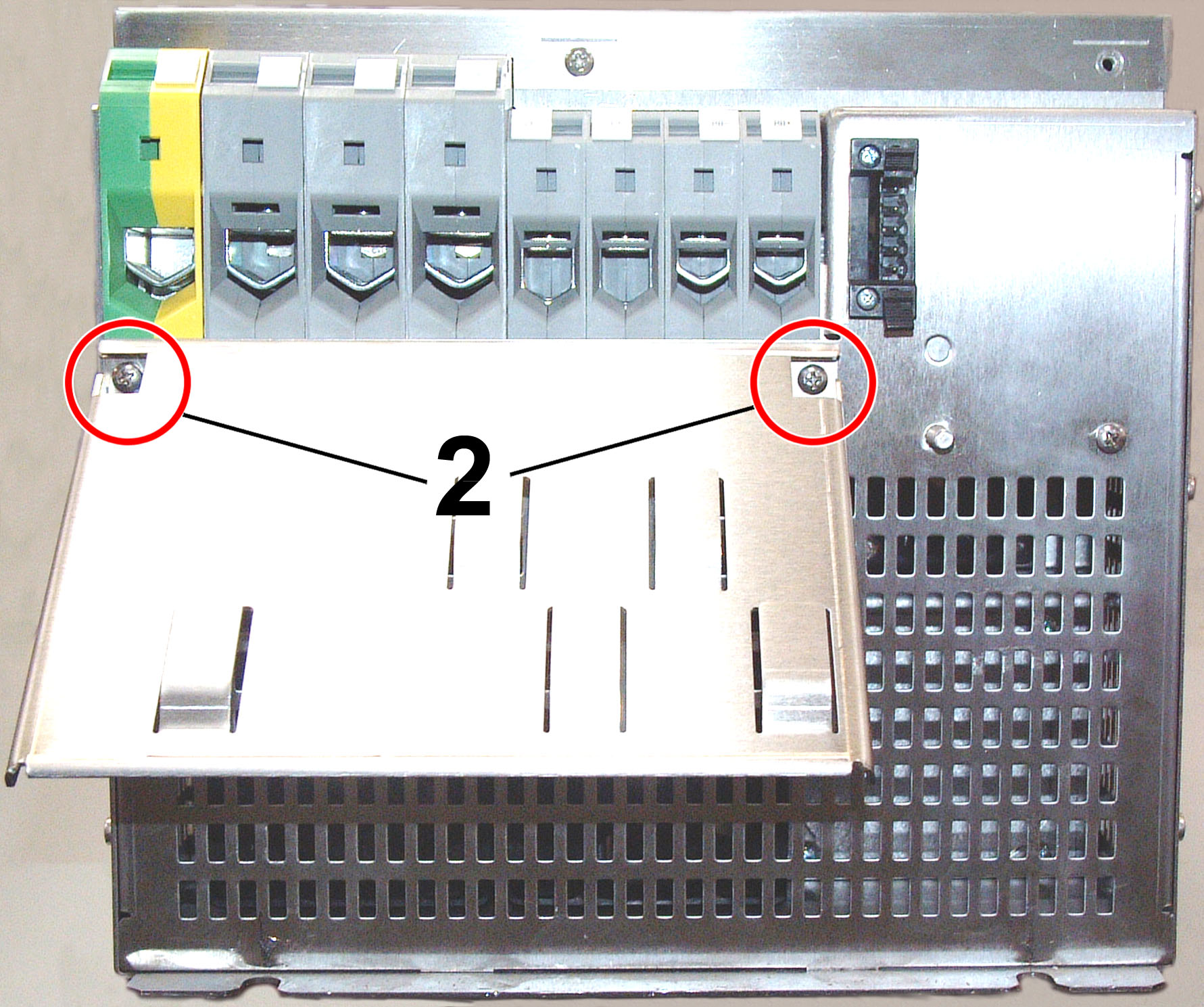
Shielding bracket installation:
2.) Position the shielding bracket.
3.) Fasten the shielding bracket with the screws (2).
Only use the screws included in the scope of delivery of the shielding bracket set for installation.
4.) Connect the cables to the terminals provided. Attach the shield to the tabs.
AX5192 and AX5193
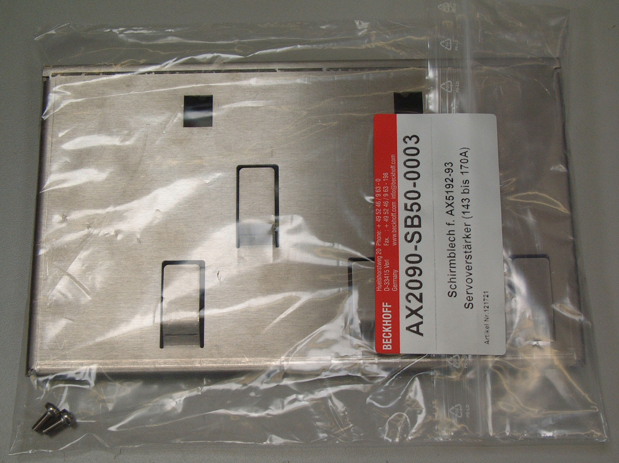
AX2090-SB50-0003:
Shielding bracket set for AX5192 and AX5193 consisting of shielding bracket and screws (2 M4 x 10).
Preparation for installation:
1.) Remove the 2 pre-assembled screws (1).
Shielding bracket installation:

2.) Position the shielding bracket.
3.) Fasten the shielding bracket with the screws (2).
Only use the screws included in the scope of delivery of the shielding bracket set for installation.
4.) Connect the cables to the terminals provided. Attach the shield to the tabs.