Presentation AX5160, AX5172
The servo drive shown below is an AX5172; the AX5160 is identical.
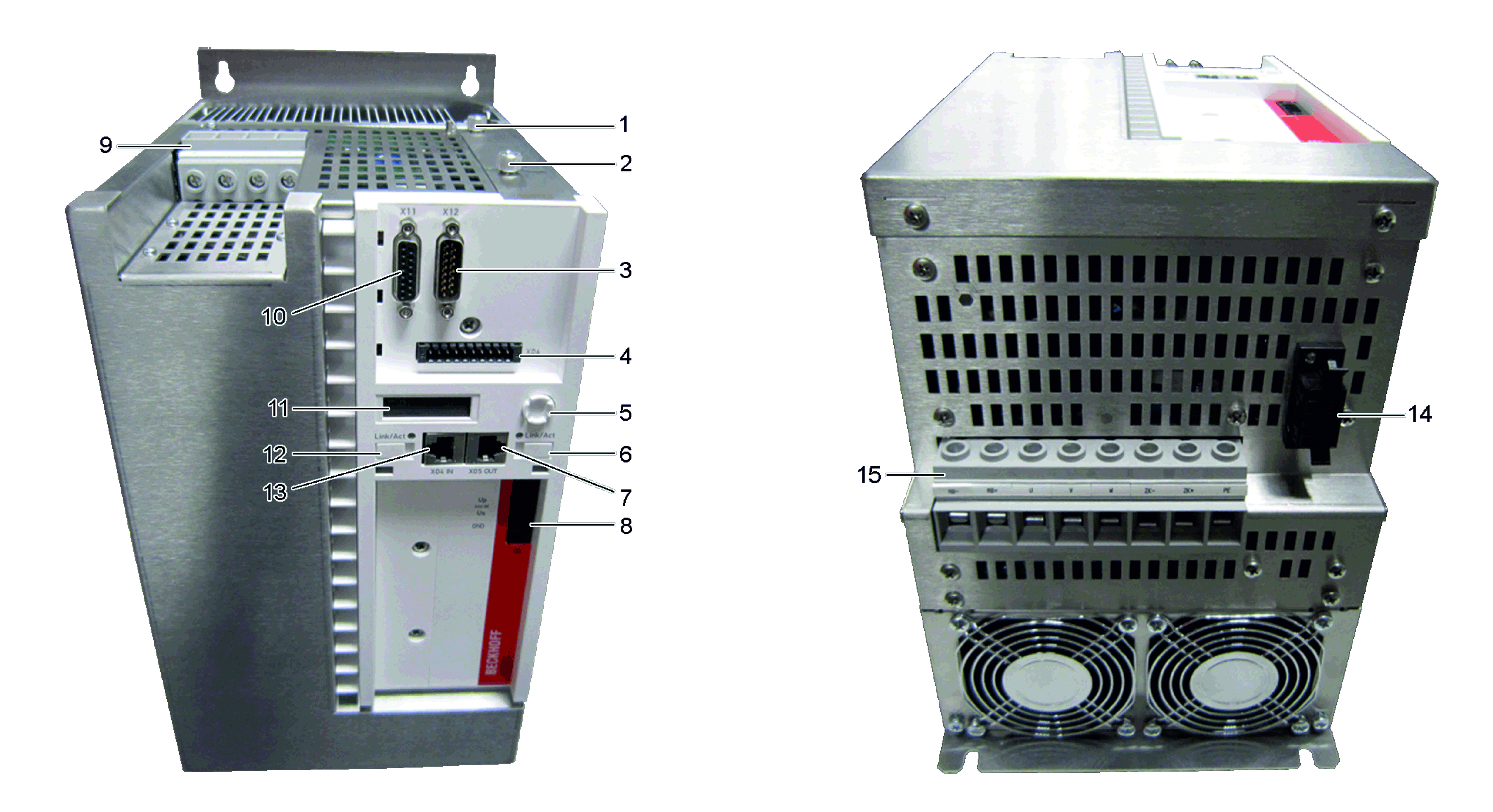
No. | Name | No. | Name |
|---|---|---|---|
1 | X4x – option slot for expansion cards | 9 | X01 – mains supply 400 V – 480 V |
2 | X3x – option slot for safety card | 10 | X11 – feedback connection, encoder |
3 | X12 – feedback connection, resolver | 11 | Display |
4 | X06 – connection for digital inputs/outputs | 12 | Labeling field |
5 | Navigation rocker | 13 | X04 – socket for EtherCAT input |
6 | Labeling field | 14 | X14 – sensor for motor temperature and brake |
7 | X05 – socket for EtherCAT output | 15 | Connection for the external braking resistor DC link output (875 V DC voltage). Motor connection (U, V, W, PE) |
8 | X03 – power supply, 24 V DC input |
| |
Serious risk of injury due to high electrical voltage! Due to the DC link capacitors, the DC link terminal points “DC+ and DC-” and “RB+ and RB-” may be subject to life-threatening voltages exceeding 875 VDC, even after the servo drive was disconnected from the supply network. |
