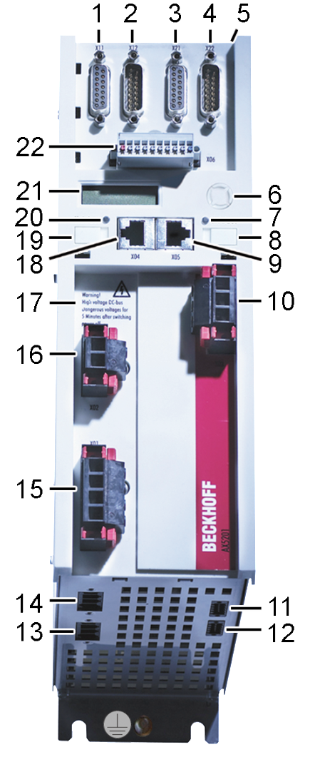
General overview AX5101…AX5112 and AX520x
The servo drive shown below is a 2-channel device. Components that are only available for the second channel are identified in the item description.
Position | Name |
| |
|---|---|---|---|
1 | X11 – Feedback connection, encoder |
| |
2 | X12 – Feedback connection, resolver | ||
3 | X21 – Feedback connection, encoder Channel B (only for 2-channel unit) | ||
4 | X22 – Feedback connection, resolver Channel B (only for 2-channel unit) | ||
5 | X3x – Optional slot for safety card X4x – Option slot for expansion cards | ||
6 | Navigation rocker | ||
7 | Status LED for EtherCAT output | ||
8 | Labeling field | ||
9 | X05 – Socket for EtherCAT output | ||
10 | X03 – Power supply, 24 V DC input | ||
11 | X14 – Sensor for motor temperature and brake | ||
12 | X24 – Socket for Thermal Contact and Brake Channel B (only for 2-channel unit) | ||
13 | X23 - motor connection (U, V, W, PE) Channel B (only for 2-channel unit) | ||
14 | X13 - motor connection (U, V, W, PE) | ||
15 | X01 | Mains supply 100…480 V | ||
16 | X02 – DC link output Connection for the external braking resistor | ||
17 |
WARNING | 875°V°DC Voltage at the DC link terminals X02. After the unit is shut down a life-threatening voltage remains for 5 minutes. The device is safe once the voltage has fallen below 50 V. | |
18 | X04 – socket for EtherCAT input | ||
19 | Labeling field | ||
20 | Status LED for EtherCAT input | ||
21 | Display | ||
22 | X06 – Connection for digital inputs/outputs | ||