Control
The motor brake is generally controlled automatically via the AX5000 servo drive. For manual control, the "Manual brake control" service function must be selected in the TC3 Drive Manager. This function is described later in this chapter.
Flow diagram for the motor brake control
The following diagram shows the temporal and functional relationship between the enable signal and opening and closing of the motor brake.

Pos | Enable process description |
| Pos | Disable process description |
|---|---|---|---|---|
1 | The controller (NC) issues an enable request for the holding brake to the AX5000 servo drive. |
| 1 | The target speed and the actual velocity approach standstill. |
2 | The control loop of the AX5000 is activated (vtarget = 0). |
| 2 | The servo drive detects the standstill of the axis with the aid of the standstill window |
3 | The brake output at the servo drive is now triggered. |
| 3 | The controller (NC) disables the axis. The AX5000 servo drive continues to control with it vtarget = 0. The axis now no longer follows the setpoints of the controller (NC). Bit 3 in the status word is set to 0. |
4 | When the "Drive on delay time" (S-0-0206) has elapsed, the servo drive follows the setpoints of the controller. This sets bit 3 in the status word (NC). |
| 4 | The brake output for the motor brake is now disabled. |
5 | The controller (NC) now specifies a travel profile for the servo drive. |
| 5 | When the "Drive off delay time" (S-0-0207) has elapsed, the controller in the AX5000 is disabled. |
6 | The standstill flag changes its status from 1 to 0, since the axis is now in motion. |
| 6 | The drive control is now fully disabled. |
Notice | |
Weight counterbalance! If the axis drops on enable, the weight counterbalance should be activated with S-0-0163. Enter the current value required by the drive for holding the axis. For a stationary axis this can be read in parameter S-0-0084. |
Manual control of the motor brake for testing purposes
In order to use the service function of the TC3 Drive Manager for the motor brake, select it in the TC3 Drive Manager under "Service functions → Manual brake control".
Default setting
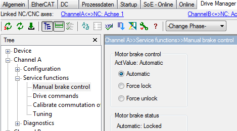
The default setting of the motor brake is "Automatic". The enabled mode is displayed under "ActValue" (current value). If it differs from your selection, the text is shown in red.
The current status of the motor brake is shown under "Motor brake status". It can be "Locked" or "Unlocked".
The status changes when a new start-up list is downloaded.
"Force unlock" option
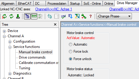
The motor brake is unlocked via the command "Force unlock".
Unlock the holding brake as follows:
- Activate Force unlock
- Press the Download button
 .
.
The change is activated via the "Download" button. It contains your new settings.
You have successfully unlocked your motor brake.
Controlling the motor brake for special application requirements
The parameters P-0-0096 (motor control word) and P-0-0097 (motor status word) are available for situations where the motor brake has to be controlled from within the application. The following table shows the command sequence for unlocking and locking the brake from the PLC.
Unlocking the brake | Locking the brake | ||
|---|---|---|---|
Control word (P-0-0096) | Status word (P-0-0097) | Control word (P-0-0096) | Status word (P-0-0097) |
| 0x0000 |
| 0x0000 |
0x0002 |
| 0x0001 |
|
| 0x0003 |
| 0x0000 |
The PLC function block FB_SoEAX5000SetMotorCtrlWord is available for simplified control of the motor brake.