Position offset
 | Terminology In this documentation, the term offset tends to be used to describe the function of the position offset. |
An offset can be configured if an absolute encoder is used in the AX5000. The value can be stored in the motor encoder, in the AX5000 or in the startup list. The offset is taken into account when the AX5000 starts up. It is added to the absolute encoder position. The result is reported to the higher-level controller as an actual value.
In contrast to the offset stored in the TwinCAT NC, the offset stored in the AX5000 or in the encoder can also be modified and stored from the PLC (see procedure described below).
Parameters involved
The meaning of the parameters in relation to the offset is explained in the following chapters.
| Reference values of the position offset S-0-0051; P-0-0159, P-0-0271; P-0-0272; P-0-0273; P-0-0274; P-0-0275; P-0-0278 |
Requirements
The AX5000 requires firmware v2.06 build 8 or higher. For positioning, an absolute encoder must be connected to the AX5000. The offset can also be used with a single-turn encoder or a resolver, which use an absolute counting method within a revolution.
Procedure
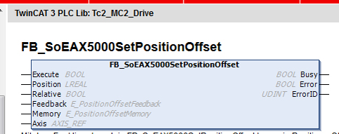
A PLC function block is available in the library
TC2_MC2_Drive
under TwinCAT 3 for saving or modifying the offset from a user program:
The description of this PLC function block can be found in the Beckhoff Online Infosys, for example.
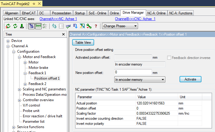
The offset is stored in increments. The TC Drive Manager should therefore be used for entering or modifying the offset without a PLC program. It deals with the conversion between user units and increments. The following page becomes active, if the AX5000 is linked with an NC axis:
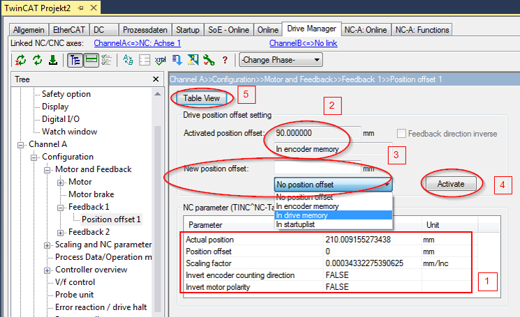
It shows settings from the NC (1) and whether an offset is already active (2). To save a new offset, enter the value in user units and select the storage location (3). Use the "Activate" button (4) to store and enable the offset. The "Activate" function can only be executed if the axis is not in controlling mode.
If the AX5000 is linked to a CNC axis, the TC Drive Manager does not "know" the feed constant. The window shows fewer data, and the offset must be entered in increments.
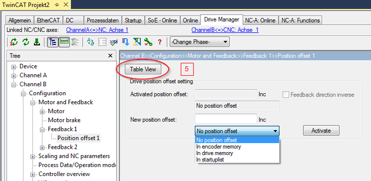
The "Table View" button (5) can be used to switch the view in both cases (NC or CNC) (see figure below).
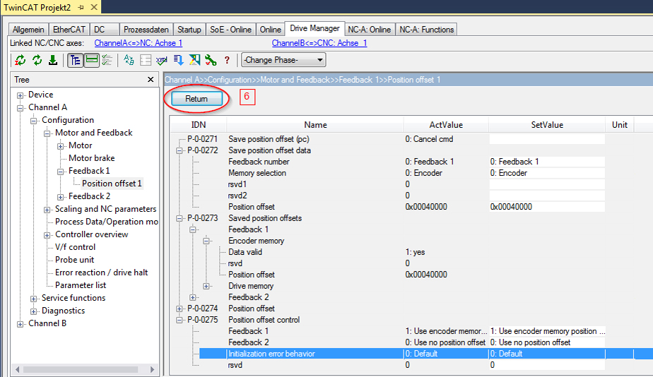
The parameters involved and their current values are displayed here. Use the "Return" button (6) to return to the original view (top figure).
Behavior when components are replaced
If a faulty motor or servo drive (AX5000) is replaced, the axis should be prevented from starting with an incorrect offset, which could result in damage. The following scenarios are conceivable, depending on where the offset is stored and which component is replaced:
Offset stored in encoder (P-0-0275 "Use encoder memory position offset") | |
|---|---|
Replaced | Result |
Motor: | EtherCAT Status: Err PreOp |
Motor: | EtherCAT Status: Op |
Servo drive AX5000 (with or without stored offset) | EtherCAT Status: Op |
Offset stored in AX5000 (P-0-0275 "Use drive memory position offset") | |
|---|---|
Replaced | Result |
Motor: | EtherCAT Status: Err PreOp |
Motor: | EtherCAT Status: Err PreOp |
Servo drive AX5000: | EtherCAT Status: Err PreOp |
Servo drive AX5000 (with or without stored offset) | EtherCAT Status: Err PreOp |
Delete position offset
To delete a stored offset, enter the value 0 and select the memory location to be deleted (encoder or servo drive):
Click "Activate" and confirm the error message that appears (see figure below) with OK: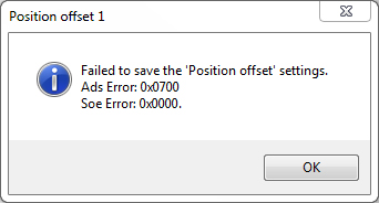
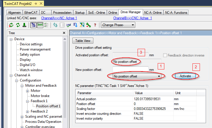
Then select "No position offset" (1) and click "Activate" (2) again. The display (3) then switches to "No position offset".