Acceleration pre-control
The lag error of an axis during acceleration can be minimized with the aid of the acceleration pre-control. This can, for example, shorten the cycle times of handling axes or improve path accuracy for CNC axes.
The meaning of the parameters in conjunction with the acceleration pre-control is explained in the following chapters.
 | Reference variables for the acceleration pre-control P-0-0010, P-0-0071, P-0-0505, P-0-0556, S-0-0348 |
Requirements
Acceleration pre-control can only be used if the AX5000 is in operation mode
- 11: position control feedback 1 lag less
or
- 12: position control feedback 2 lag less is operated.
The AX5000 receives a new position setpoint cyclically (e.g. every 2 ms) and interpolates between the new setpoints with the cycle time of the position controller (default value 250 µs).
The acceleration results from the second derivative of the position. In the case of linear interpolation of the setpoints the value of the second derivative is always zero.
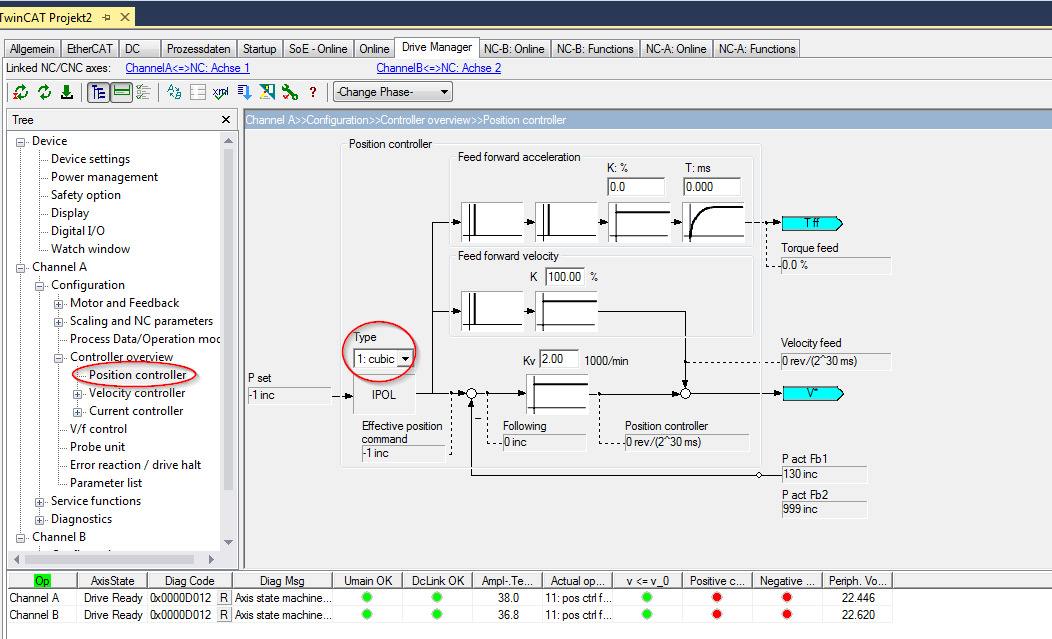
Therefore cubic interpolation must be set in the AX5000 (P-0-0556).
If cubic interpolation is active, the cycle time of the position controller in the AX5000 (P-0-0004) must not be shorter than 250 µs, otherwise an error message (F330) will appear.
The acceleration pre-control should be used if possible with a firmware version ≥ FW v2.10 build 8. The function has already been implemented in previous versions, but not with the functionality described here.
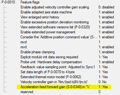
In parameter P-0-0010 "Feature Flags", the associated bit must be activated so that the scaling of the pre-control takes place in %:
A value for the current is calculated from the acceleration, depending on the motor and the load conditions. For this, it is important that the correct values for the mass inertia of the motor and the load are entered in parameter P-0-0071:
The mass inertia of the motor is read automatically from the electronic nameplate during the configuration.

If the exact value of the load inertia is not known it should be estimated. In most servo applications the ratio of the load inertia to the motor inertia has a value of between 3 and 10.
Procedure
First of all, optimize the axis with the linear interpolation. To do this, record the current, velocity command value, actual velocity and lag error with the oscilloscope.
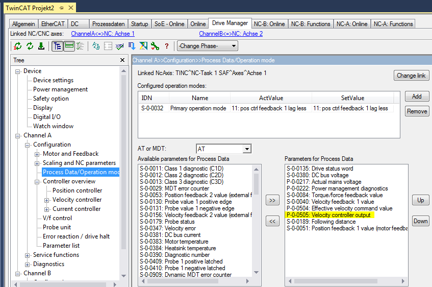
Then activate the cubic interpolation as shown above and add the parameter P-0-0505 to the process data:
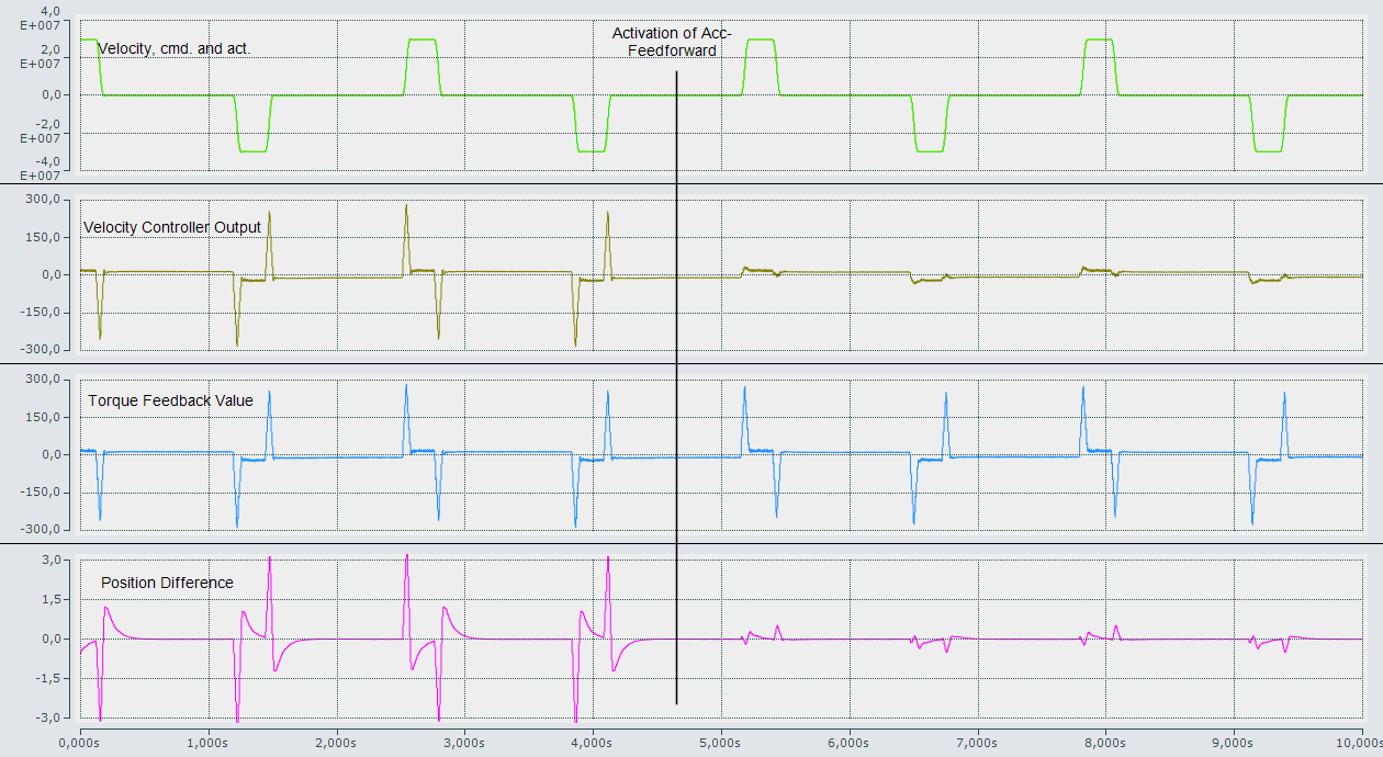
If you record the value of the "velocity controller output" with the oscilloscope, you will obtain a picture similar to the one shown here:
The value of the "velocity controller output" (P-0-0505) is largest during the acceleration and braking phases.
In the second part of the picture the acceleration pre-control is active. As a result, the velocity controller is relieved and the value of the "velocity controller output" reduced.
At the same time the lag error becomes smaller.
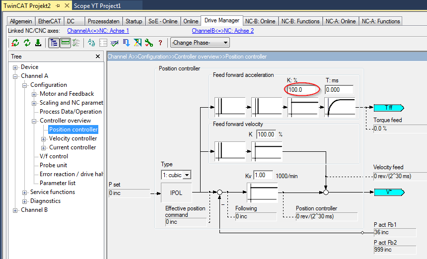
If the mass inertia is correctly set, a value of 100% is ideal in the normal case for the acceleration pre-control
(S-0-0038, "acceleration feedforward gain"):
This can be checked and corrected if necessary using the oscilloscope recording.
The criterion for this is the size of the lag error and possibly the value of the "velocity controller output".