Commissioning
| |
Danger due to uncontrolled motor movements During the initial commissioning of a third-party motor, the motor may perform uncontrolled movements.
|

Checking the position display
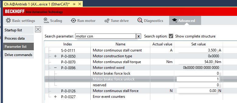
If you can rotate the motor shaft by hand, check whether meaningful position values are displayed. If there is a brake, it can be released with the help of the parameter P-0-096, "Motor control word". Set "Motor brake: force unlock" to the value "1".
 | Do not initially change the direction of rotation by means of the parameters, neither in the feedback settings nor for the NC axis! The assignment of the counting direction to the application takes place only at the end of commissioning. |
Checking the direction of rotation
With the command P-0-0166 you can check whether the connection of the motor phases matches the counting direction of the feedback system.
| |
Danger due to uncontrolled motor movements The motor performs a movement when the command is executed!
|
In the Drive Manager, select the "Advanced" tab [1], then "Drive commands" [2]. From the list of commands, select "P-0-0166: Motor and feedback connection check" [3] and, in parameter P-0-0167, which is displayed below, select the "Results" entry [4].
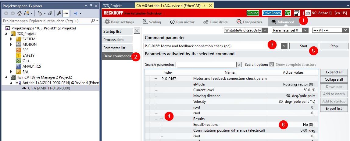
The execution of the movement is started by clicking Start [5]. The first time after restarting, you will be asked:
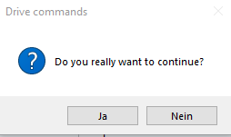
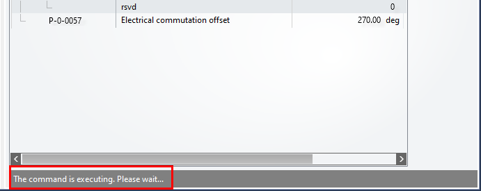
Continue with "Yes". Below the parameter window, a status bar informs you about the execution of the command:
If possible, observe the motor to confirm that the shaft is moving. After successful execution of the command, the status bar displays:
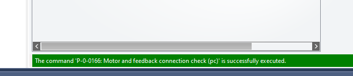
Now check the "Equal directions" entry in "P-0-0167 / Results" (see above [6]). If "Yes" has been entered there, the counting direction of the feedback system matches the connection order of the motor phases. If it reads "No", either the counting direction of the feedback or the order of the motor phases must be changed.
We recommend executing command P-0-0166 several times while observing the motor. Necessary changes should be carried out or commissioning continued only when it is has been ascertained that the motor is moving and the result is reproducible.
If the feedback counts as described above (positive clockwise), it is recommended in case of a "No" result, for example, to swap the connections for phases U and V on the motor connection plug X13 / X23.
| |
Danger from live components Live components can come into contact with the tool when changing phases. This can result in serious or even fatal injuries.
|
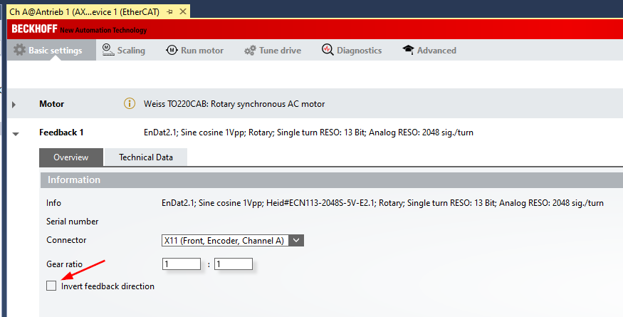
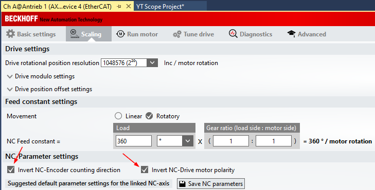
The counting direction of the feedback can be changed in parameter P-0-0150. The Drive Manager allows this change to be made with the checkbox "Invert feedback direction" under "Basic Settings / Feedback 1":
Determining the electrical commutation offset
The electrical commutation offset is also determined with the help of command P-0-0166. Start the command again, make sure that "Yes" is displayed again in "Equal directions" under "P-0-0167 / Results" [1] and read the value for "Commutation position difference (electrical)" [2]:
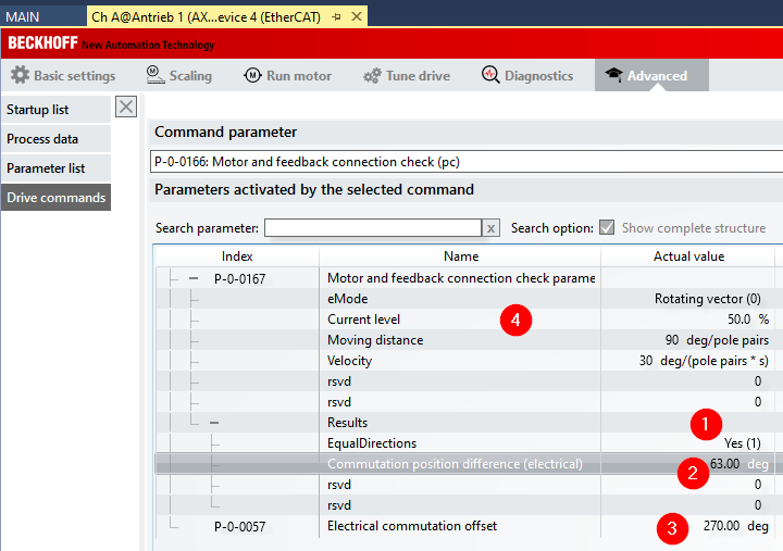
Subtract this value from the value in P-0-0057 "Electrical commutation offset" [3]. The result is the new value for "Electrical commutation offset".
Example: Electrical commutation offset (new) = 270° - 63° = 207°.
If the result of the subtraction is < 0, add 360° to get a value between 0° and 360°.
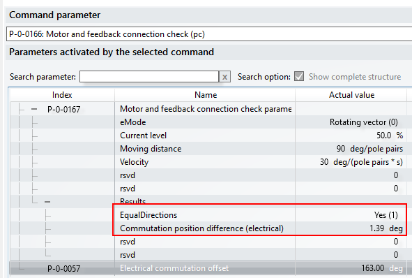
After entering the new value, start the command P-0-0166 again. After successful execution, the value for "P-0-0167 / Results / Commutation position difference" should be in the range 350°... 360° or 0°... 10°.
It is a good idea to execute the command several times and to correct the offset if necessary. In the case of stiff axes, increasing the current for the execution in "P-0-0167 / Current level" (see above [4]) can provide for more reliable results.
For the most reliable results, these determinations should be carried out without load on the motor shaft.
Configuration of the Wake & Shake routine
If the motor is equipped with an incremental encoder, the commutation offset must be redetermined each time after restarting the AX5000. This is done with the help of the Wake & Shake routine. The prerequisite for the routine to work is that the motor phases match the counting direction of the encoder as described above. Details of the process for finding the commutation with "Wake&Shake" can be found in the Beckhoff Information System under the keyword: "Electronic commutation".
The command P-0-0160 executes the routine. The type of execution can be set in parameter P-0-0165:
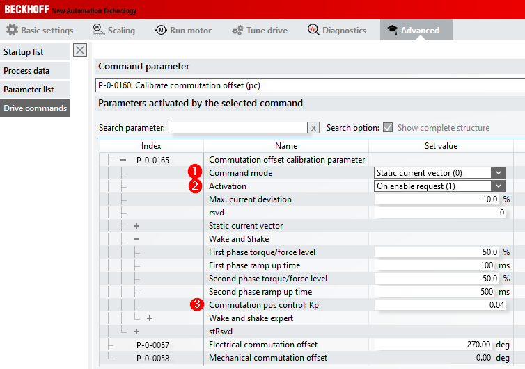
In "Command mode" [1] you can choose between:
- 0: Static current vector and
- 1: Wake and Shake
The "Static current vector" procedure results in a larger motor movement. It can be used for testing.
The "Wake and Shake" procedure minimizes the axis movement. This procedure is the one that tends to be used in practice.
Both procedures determine a commutation offset, although this is not shown in parameter P-0-0058. The value must be redetermined each time when restarting and depends on the axis position.
It is therefore meaningless for the user.
The result can then be checked with the command P-0-0166. Both procedures should initially be performed with the default values.
The setting "Activation : On enable request (1)" [2] has the effect that the AX5000 automatically executes a commutation search with the first enable after a restart.
With "Wake and Shake" it is often useful to set "Commutation pos control: Kp = 0" [3]. The motor may perform a slightly larger movement. The tendency to oscillate during the execution of the routine decreases.
Diagnostic options
In the event that a commutation offset cannot be determined reproducibly or the motor cannot be moved reliably despite the apparently correctly determined commutation offset, this chapter describes options for diagnostics with the TwinCAT ScopeView.
The description assumes that an empty measurement project of type "YT Scope Project" exists and that you know how to add new axes and signals.
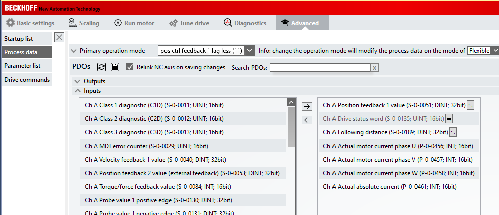
Process data
Add the following parameters to the process data of the AX5000:
- P-0-0456, Actual motor current phase U
- P-0-0457, Actual motor current phase V
- P-0-0458, Actual motor current phase W
- P-0-0461, Actual absolute current
Activating the ADS server
In order to be able to add the parameters with the Target Browser in ScopeView, the ADS server has to be activated:
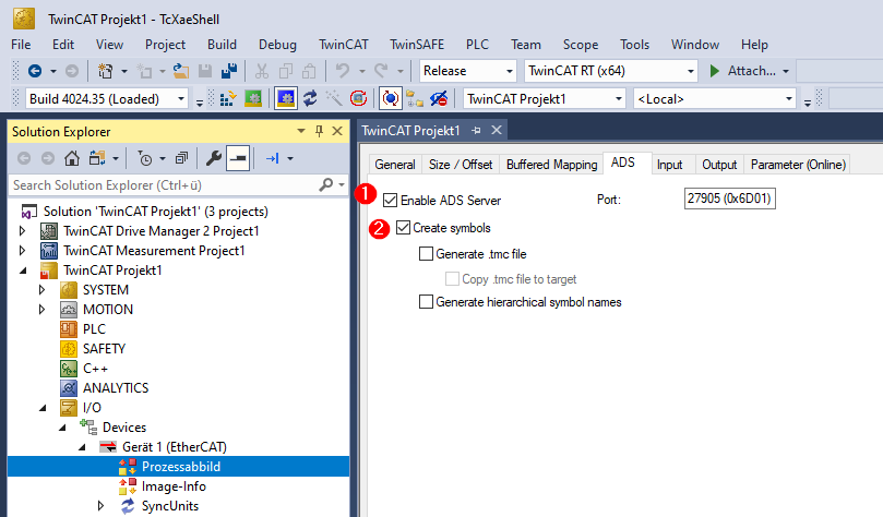
Check the checkboxes "Enable ADS Server" [1] and "Create Symbols" [2]. You have to activate the TwinCAT configuration in order for these changes and the added process data to take effect.
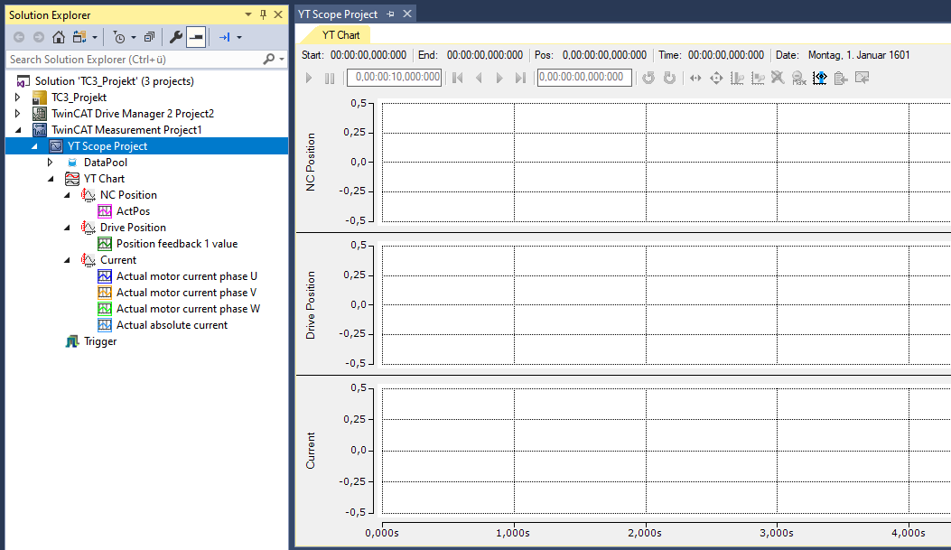
Setting up Scope View
Set up ScopeView as follows:
Settings for the command P-0-0166
The motor movements executed with the command P-0-0166 can be defined with the values in parameter P-0-0167. Change "Moving distance" to "360 deg". The other settings are appropriately preset for most cases:
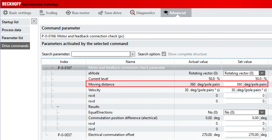
Thus, the current vector will perform an electrical revolution. The expected rotor movement depends on the number of pole pairs of the motor:
Movement = 360° / number of motor pole pairs
Number of pole pairs | Expected rotor movement [deg] |
|---|---|
3 | 120 |
4 | 90 |
5 | 72 |
6 | 60 |
First start the recording with ScopeView. Then start the execution of command P-0-0166. The following recording shows the correct behavior of the motor with 3 pole pairs at "Moving distance = 360 deg".
Sequence of command P-0-0166
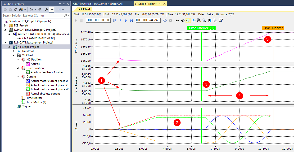
The execution of the command begins after about 1.5 s [1]. This can be seen in the fact that the current value (red line, "Actual absolute current") increases and the position changes slightly. The rotor aligns itself. The movement depends on how the rotor was standing. The current rises to the set value and remains constant over the set time [2]. The vector then begins to rotate around the specified electrical angle [3], 360° in the example. In the recording, this can be seen in the curve of the phase currents and the change in position [4]. Because a movement distance of 360° was specified, the individual phase currents each pass through 360°. The execution of the command is finished shortly before the Time Marker [5].
Evaluation
As described above, a movement of the rotor by 120° is expected in the example. The scaling factor for the axis is set to 360°. Therefore, the rotor movement in the NC position can be read in "°":
Determine the difference in position by which the rotor was moved during the execution of the command. This is possible, for example, with the help of the Time Markers and the Marker Window:
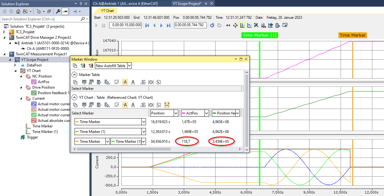
The position of the NC axis has changed by 118.7° in the example. That is close enough to the expected 120°.
The value of the "Position feedback" from the process data has changed by 3.459E+05.
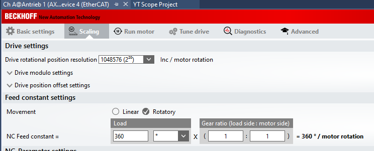
From the resolution of 220 = 1048576 incr. / motor revolution, this results in:

Possible error scenarios
- The rotor does not move by the expected difference.
- Check the number of motor pole pairs! Did the motor move twice as much as expected? Then the number of pole pairs was probably confused with the number of poles.
- Can the motor shaft rotate freely, or is the movement mechanically blocked/braked?
- The phase current curves are asymmetric.
- Check the electrical connection of the motor phases!
- The position in area (4) doesn't become larger during the execution of the command, but smaller.
- If the direction of rotation for the NC axis was inverted, "Position feedback" (process data) and "Actual Position" (NC) count in opposite directions.
- The position value from the process data is decisive. The connection order of the motor phases is incorrect or the feedback is counting in the wrong direction. What does "Equal Directions" in "P-0-0167 / Results" show?
- The position values from the axis and those from the process data result in movements of different distances.
- Check the resolution of the feedback!
- In the case of encoders with sin/cos signals: is the number of sine periods per revolution correct?
- In the case of resolvers: is the number of resolver poles correct?
- Check the scaling factor of the NC axis!
Change in the feedback parameter P-0-0150
Under "Advanced / Parameter list", select the parameter P-0-0150, e.g. with the help of the search function [1].
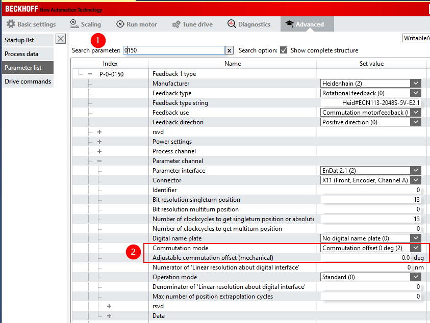
Change "Commutation mode" from "No commutation position (0)" to "Commutation offset 0 deg (2)" [2]. If there is a different entry there and a value of > 0.0 deg is entered in "Adjustable commutation offset (mechanical)", we recommend that you enter the value 0.0 deg and redetermine the electrical commutation offset by following the steps described above. Otherwise a mixture of mechanical and electrical offset will be used.
- Notes:
- Changes in parameter P-0-0150 only become effective on activating the configuration.
- If this change is not made, the AX5000 will display the error message "F107, Axis state machine: Current control not ready to enable" when attempting to switch the axis to control ("Enable").