Selection and input of the data
Selection of the motor type
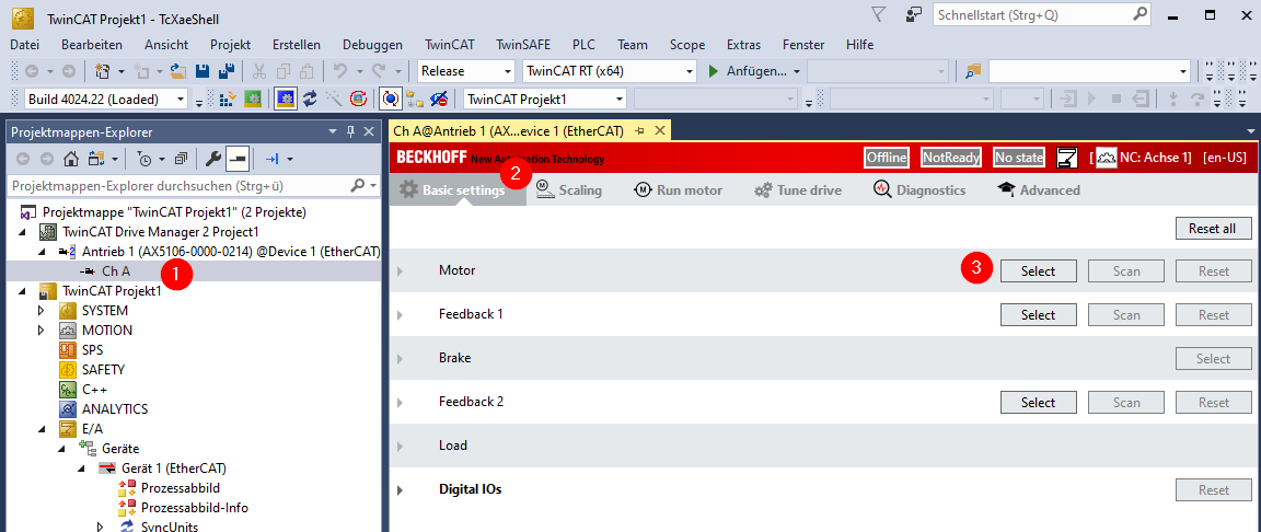
In your Drive Manager project, select the channel of the servo controller to be parameterized [1], then the "Basic Settings" tab [2] and, in the "Motor" row, the "Select" button [3]:
In the "Select a Motor" window which then opens, select the options "Third party" [1], "Manual input" [2]. The parameters for a rotary [4] synchronous motor [3] are described below. Please select whether or not the motor has a holding brake [5].
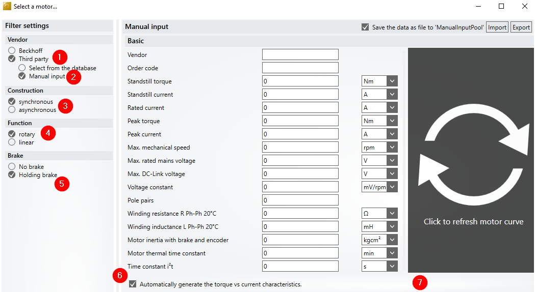
If you leave the checkbox "Automatically generate the torque vs current characteristics" [6] checked, a characteristic curve of the motor [7] will be displayed to the right of the table after entering the motor data. We recommend that you leave the checkbox checked. Some inadvertent incorrect data entries can quickly be spotted in the characteristic curve.
Input of the motor parameters (for a rotary synchronous motor)
- "Vendor" and "Order code" are designations and have no effect on the function of the motor. The parameter file is saved under these designations and appears to the motor if it is recommissioned.
Please take the following parameters from the data sheet for the motor. The units behind the input boxes are usual in data sheets, but can be changed if the units are different.
 | Current values must be entered as RMS values (not peak value). |
- "Standstill torque"
- If no separate values are specified for "Standstill current" and "Rated current", enter the same value for both.
- "Peak torque" and "Peak current" are important for the creation of the characteristic curve and thus for the correct handling of the motor. If necessary, "Peak torque" can be estimated with the help of the peak current and the torque constants. "Peak current" is important to avoid overloading the motor.
- If there is no specification for "Max. mechanical speed" in the motor data sheet, enter a speed that is larger than that required in the application.
- "Max. rated mains voltage" is the maximum permissible AC supply voltage. Usual values are 230 V, 400 V or 480 V.
- "Max. DC Link voltage" is a DC voltage value that can occur briefly, but not constantly. The AX5000 will signal an overvoltage error if this value is exceeded.
 | When supplied with 400 VAC, the DC link voltage is 560 VDC. During braking, the motor feeds energy back and the DC link voltage increases until the braking resistor is switched on if necessary. The value for the maximum permissible DC voltage must be higher than the switch-on threshold for the braking resistor and must therefore not be too small. The default value is 890 VDC. At this value the AX5000 switches off with an error message. This is not a problem for most motors that are designed for operation on 400 VAC. If the motor is not approved for that, enter a lower value, e.g. 750 VDC. The AX5000 outputs a parameter error (F4A5) if the value entered is too low. |
- The "Voltage constant" of the motor is also required for the creation of the characteristic curve and thus for the correct handling of the motor.
- Select the correct units. If Vs/rad is specified, select Vs!
- When entering the "Pole pairs", make sure you enter the number of pole pairs and not the number of poles.
- The values measured from phase to phase are required for "Winding resistance R Ph-Ph 20°C" and "Winding inductance L Ph-Ph 20°C". If values for a single winding are specified in the motor data sheet, double the values! These values are used to set the control parameters for the current controller.
- "Motor inertia with brake and encoder": This value is included in the calculation for the control parameters of the speed controller.
- "Motor thermal time constant": The software uses this value to calculate the thermal model of the motor for protection against thermal overload.
- "ime constant i2t". If a value is available, it is also included in the calculation of the thermal motor model. Because it is not specified in most motor data sheets, the value "0" can remain in the table. The thermal model is then calculated using only the "Motor thermal time constant".
Input of nominal points
Under "Nominal Points" you can enter one or more nominal points of the motor at different voltages in order to describe the characteristic curve in more detail:
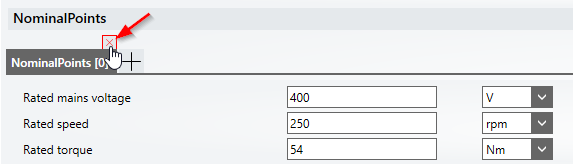
If you cannot enter a nominal point, close the window with the corresponding cross, which becomes visible when hovering over it with the mouse cursor (see picture above). No characteristic curve is displayed as long as the window is open and not filled out.
Input of the temperature sensor
If the motor has a sensor for monitoring the winding temperature, check the checkbox "Motor temperature sensor or switch":
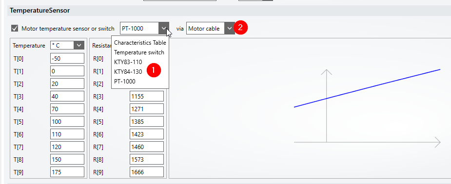
Select the correct sensor [1] and its connection [2] from the selection list.
Please note the following:
- Most sensors can only be connected to X14 / X24 on the underside of the AX5000. The correct selection for this is "Motor cable".
- Only the evaluation of a temperature switch is possible on the feedback connector (X12 / X22). Shutdown with motor overtemperature takes place at about 1.3 kOhm.
- Depending on the selection, the software generates a characteristic curve, displays it and enters value pairs in the table. (The values are entered in parameter P-0-0076).
Input of the brake data
If you indicated at the start that the motor has a holding brake, you must enter its data in the corresponding window:
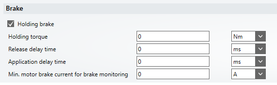
The holding torque of the brake is usually shown in the data sheet for the motor, as are the Release delay time and the Application delay time.
Depending on the value for "Min. motor brake current for brake monitoring", the monitoring of the brake is preset: when the brake is released, at least the set current must flow through the brake; otherwise, the AX5000 will trigger a brake error.
Do not enter an excessively large current value here! The current measurement is not precise and too large values trigger unnecessary errors. Half the value of the nominal brake current has proven to be useful.
| If the "Holding brake" option is activated in the "Filter settings", no motor characteristic curve is displayed until the brake data has been entered. |
Saving the motor data
After entering all motor and brake data, make sure that a meaningful characteristic curve is displayed and close the input window with "OK".
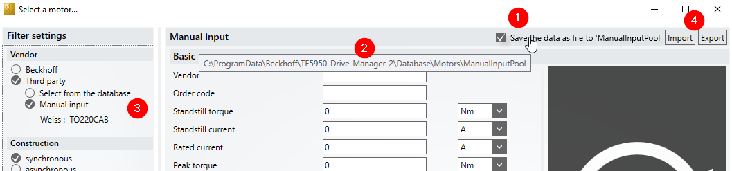
If the checkbox "Save the data as file to ManualInputPool" is checked [1], the motor data are automatically saved to a file when the input mask is closed with "Ok". The path to the directory is displayed when the mouse cursor is hovering over the text [2]:
C:\ProgramData\Beckhoff\TE5950-Drive-Manager-2\Database\Motors\ManualInputPool
Motor files previously saved there are displayed when selecting "Manual input" and can be selected directly [3].
It is also possible to export files to any storage location and import them again [4]. The files are given either the extension “dmmotor” or “xeds.”
| If you save the motor data in the "xeds" format, the file can also be used in other projects in which the "classic" TC Drive Manager is used instead of the TwinCAT 3 Drive Manager 2. This is done, for example, to configure a device that has a firmware version <2.10. This function of the TwinCAT 3 Drive Manager 2 thus replaces the former "TC Motor Data File Generator" tool. |
Selection of the feedback
Narrow down the selection with the help of the "Filter settings". Select the feedback from the list.
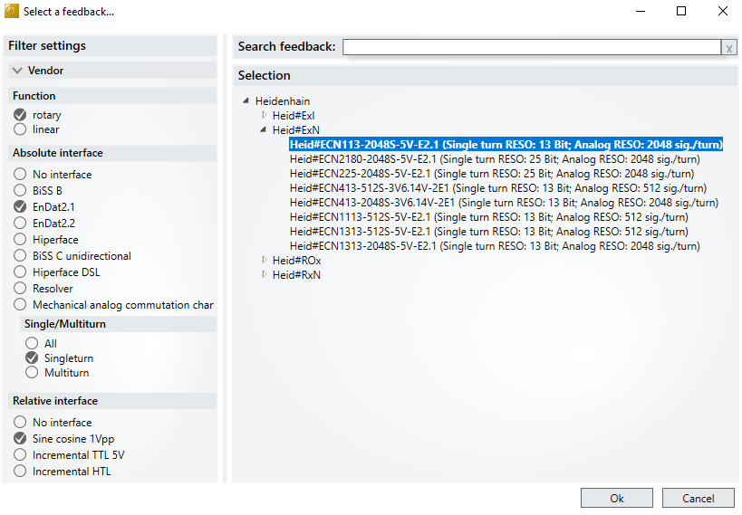
| Only encoders that have an absolute (digital) and an incremental interface can be operated on the X11 / X21 connector of the AX5000. You need the AX572x encoder option card for encoders with a purely digital interface (BISS-C, EnDat 2.2). |