Diagnostics for external brake resistors
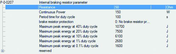
 | Reference values for the external braking resistor: P-0-0207; P-0-0208; P-0-0209; P-0-0210; P-0-0218; P-0-0219; P-0-0220; P-0-0221 |
This chapter provides basic information on dimensioning and configuration of external braking resistors. The parameters described in this chapter can be recorded with the TwinCAT Scope View for diagnostic purposes.
If an internal braking resistor is used, the configuration takes place via the IDNs:
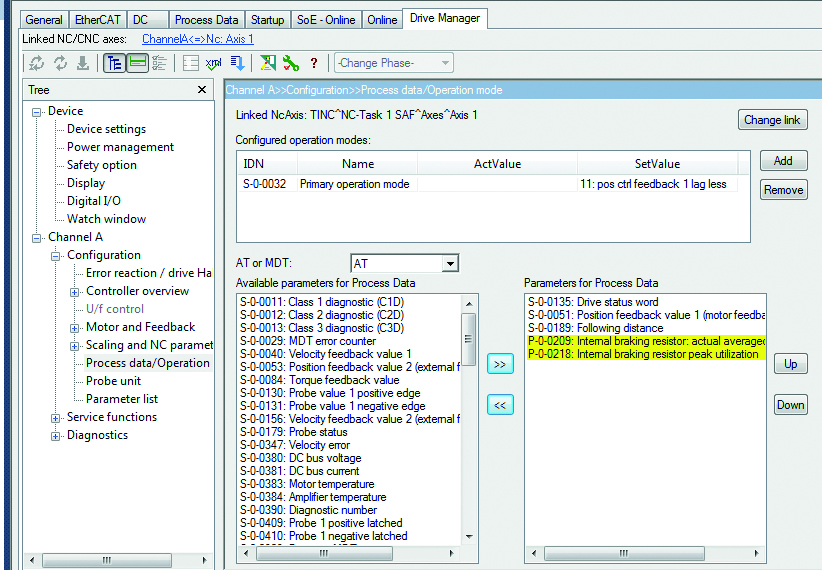
- P-0-0209 (Internal braking resistor actual continuous power) in watts and
- P-0-0218 (Internal braking resistor actual peak energy) in %
If an external braking resistor is used, the configuration takes place via the IDNs:
- P-0-0210 (External braking resistor actual continuous power) in watts and
- P-0-0219 (External braking resistor actual peak energy) in %
"Actual continuous power" is an arithmetically averaged value of the actual power. Even after several typical machine cycles the value of P-0-0210 (P-0-0209 internally) must always remain below the value of the continuous power of the braking resistor.
A cycle time of 100 s is assumed for calculating the braking resistor power. Monitoring should therefore take place over this time as a minimum. The permissible value for the continuous power can be found in P-0-0207 (internal braking resistor) or P-0-0208 (external braking resistor):
"Actual peak energy" indicates the greatest measured braking energy like a drag indicator. The situation with the maximum required peak braking power, e.g. emergency stop, is supposed to be determined and tested. In the process, the value of P-0-0218 (internal) or P-0-0219 (external) should stay considerably below 100%.
For more exact observations it is possible to record the parameters with the software oscilloscope. If for example the velocity or the position is recorded, a better allocation of the current braking power to the machine cycle is possible. To this end the parameters must be inserted into the process image beforehand:
| Further information on external braking resistors can be found at: Information on mechanical and electrical installation, dimensions and technical data can be found in the system manual for the AX5000 servo drive at: „Accessories – External braking resistor – AX2090-BW5x-xxxx“. |
For further analysis peak values are recorded in the parameters P-0-0220 (internal brake resistor) or P-0-0221 (external) with respect to the duty cycle.
Duty cycle (DC) = switch-on time / cycle time (machine cycle) x 100%
Beckhoff specifies an overload factor for the brake resistors, depending on the duty cycle (see diagram below):

Multiplied by the rated power, the permissible short-term power results from the overload factor depending on the duty cycle:
Short-term power = Rated power x Overload factor (ÜF)
For the AX5000 energy values were calculated for the supported braking resistors from the rated power, duty cycle and overload factor and saved as parameters. They can be found for the internal braking resistor in P-0-0207 and, after selecting an external braking resistor, for this in P-0-0208.
Example: AX2090BW50-1600 with 47 ohms and 1600 W rated power
Overload factor for 1% duty cycle: 30
1% duty cycle for 100 s cycle time corresponds to 1 s
1 s x 1600 W x 30 = 48000 J
Correspondingly the other saved values result:
Duty cycle [%] | 40 | 20 | 10 | 1 | 0.1 |
Overload factor | 2.2 | 3.9 | 7 | 30 | 144.375 |
Peak E. [J] | 140800 | 124800 | 112000 | 48000 | 23100 |
When the braking resistor is activated, the software calculates the current energy values based on the duty cycle and presents the maximum values in P-0-0220 and P-0-0221, respectively. Both parameters are reset when the device is restarted (=0). The values entered in operation are preserved until the next restart or until they are overwritten by the user. They can be compared with the permissible values in P-0-0207 (internal braking resistor) or P-0-0208 (external). As a result it may be possible to influence the braking power in critical regions by modifying the cycle.
The greatest percentage value is entered in P-0-0218 or P-0-0219 (in %) (see above).