Parameterization of the filter
| |
Warning, risk of injury from uncontrolled movements! Impermissible damping values lead to a strong phase shift, which can result in uncontrolled acceleration of the motor and other instable states. |

There are two different methods of parameterizing the filter.
"Classic" method
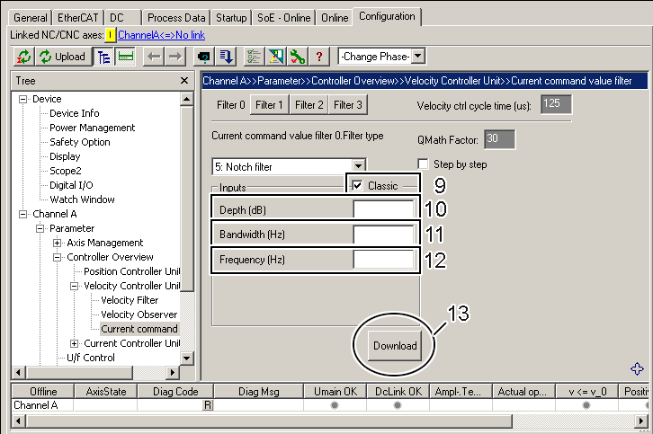
This variant is activated by checking the "Classic" checkbox (9).
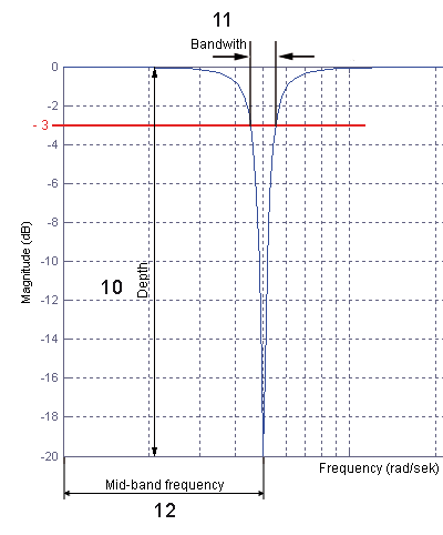
The parameters "Depth" (10), "Bandwidth" (11) and "Frequency" (12) must now be determined and entered; see the diagram "Bode Plot" below for this. The parameters entered lead internally to the calculation of the coefficients b0, b1, b2, and a1, a2 (see the above diagram "1st and 2nd order IIR filter" for this).
Click on the "Download" button (13) to conclude the parameterization. If you are online, these parameters are loaded directly into the AX5000 and activated. If you are offline, they are only written into the start-up list.
"Classic" method – "step by step"
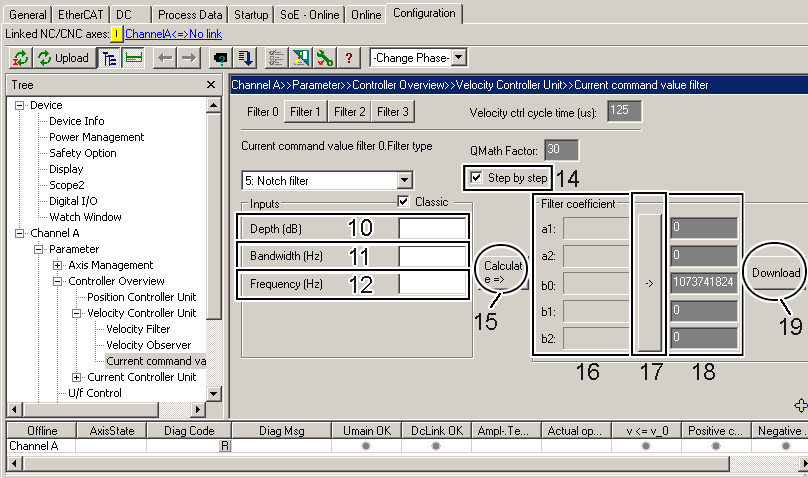
The "Step by step" extension enables you to calculate and enter the coefficients b0, b1, b2, and a1, a2 yourself (see the above diagram "1st and 2nd order IIR filter"). Among other things you can now compare the values calculated by the software with your own values and see how changing the parameters affects the coefficients.
The "Step by step" extension is activated by checking the "Step by step" checkbox (14). You can now enter the parameters (10) to (12) as described in the previous chapter, after which you click on the button (15). Subsequently, you can read off the calculated coefficients in area (16). If you wish to accept these coefficients, click on the button (17); they are now entered automatically into area (18).
Alternatively you can also determine the coefficients yourself and enter them in area (18).
If you finally click on the "Download" button (19), the values are always taken from area (18). If you are online, these parameters are loaded directly into the AX5000 and activated. If you are offline they are only written into the start-up list. The calculated values from area (16) and the parameters (10) to (12) remain visible for information purposes.
"Low pass and high pass filter" method
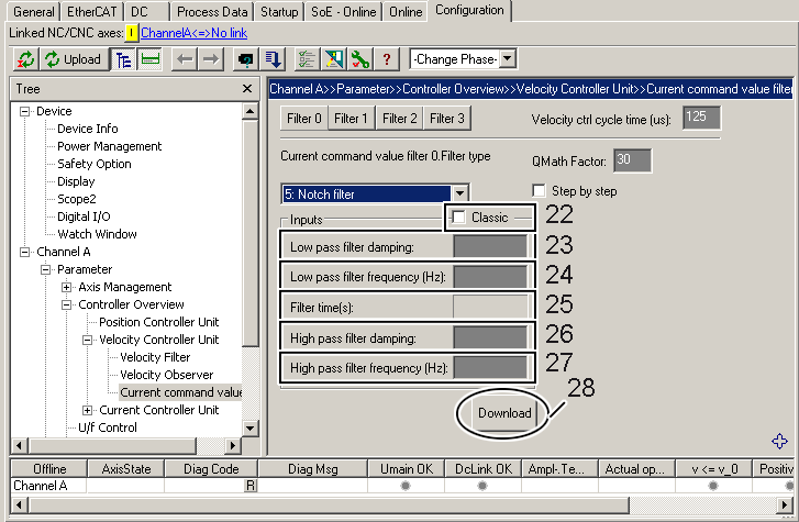
This variant is activated by unchecking the "Classic" checkbox (22).
You must now determine and enter the parameters "Low pass filter damping" (23), "Low pass filter frequency" (24), "High pass filter damping" (26) and "High pass filter frequency" (27); the "Filter time" (25) is calculated by the software in relation to the "Low pass filter frequency" (24). If you wish to emulate the classic method, you must enter the center frequency plus half the bandwidth in field (24) and the center frequency minus half the bandwidth in field (27). The depth (10) is determined with the damping (23) or (26); see the diagram "Bode Plot" below for this. The parameters entered lead internally to the calculation of the coefficients b0, b1, b2, and a1, a2 (see the above diagram "1st and 2nd order IIR filter" for this).
Using the methods described you can also map any asymmetries of the notch filter, among other things.
Click on the "Download" button (28) to conclude the parameterization. If you are online, these parameters are loaded directly into the AX5000 and activated. If you are offline they are only written into the start-up list.
"Low pass and high pass filter" method – step by step
 | Expert hint! The software calculates the coefficients independently using the parameters entered. If you have sufficient experience in control technology you can also determine the coefficients yourself and thus affect the behavior of the filter. |
The method is the same as in the "Classic method" – "step by step".
Bode Plot