Setting the "Feedback Gear Ratio"
A second example shows the setting of the feedback gear.
Application: The load is moved by a toothed belt whose pulley has a circumference of 125 mm. The motor drives the pulley via a gear with i=3.
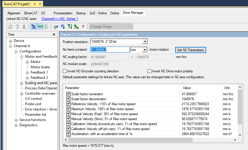
Feed constant for the first feedback:
125 mm / 3 revs. = 41.6666 mm/rev.
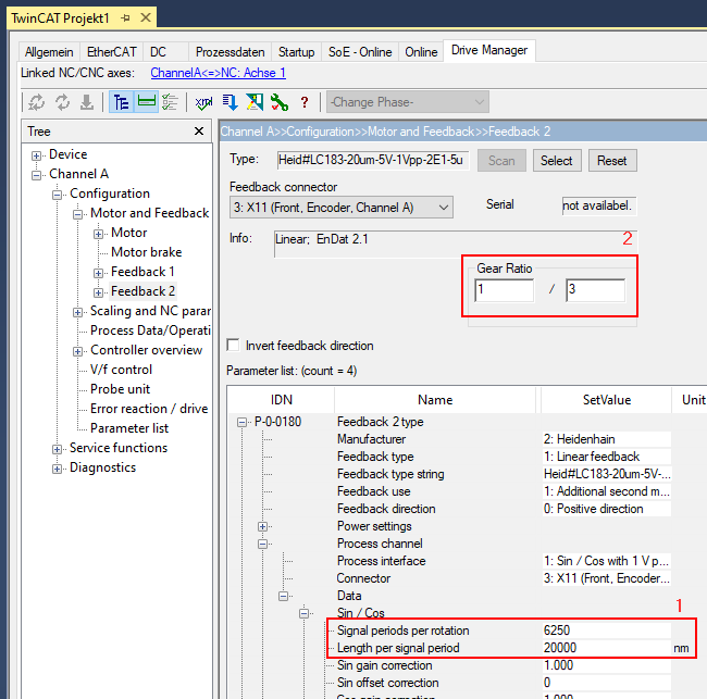
The linear encoder from the above example is used again as the second feedback.
"Signal periods per rotation" must be set accordingly:
125 mm / 20000 nm = 6250 (1)
To get the same number of increments per motor revolution, the feedback "Gear Ratio" is set to 1 / 3: (2).
With these settings, continue with Test and Enable as described above (Checking the second encoder, Enabling the second encoder).