Order of assembly of the work unit
Fastening the coil unit | |
| Observe the following notes before beginning assembly. Deviations from flatness of the surface on which the coil unit will rest must be less than 0.1 mm. The coil unit must be assembled parallel to the magnetic plate. Parallelism must be closer than 0.20 mm. The sides of the coil unit, or the round holes in the supporting surface, can be used for this purpose. Locating pins can be inserted into the round holes. Lateral positioning of the coil unit with respect to the magnetic plates is not particularly critical. A tolerance of up to ±0.5 mm is acceptable. |
Item no. | Explanation | Item no. | Explanation |
|---|---|---|---|
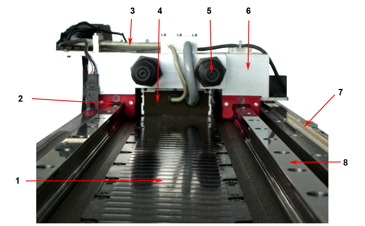
1 | Magnetic plate | 5 | Buffers |
2 | Bearing | 6 | Carriage |
3 | Cabling | 7 | Graduated rule |
4 | Coil unit | 8 | Rail |
Please note the following comments and information:
 | Order of tightening the screws: Fasten the screws in a crisscross pattern, so that the resulting forces are distributed evenly. |
Note | |
The coil unit can be damaged by incorrect screwing! Using screws that are too long for the coil unit can cause damage that is not immediately visible, and give rise to dangerous situations.
|
Screws for the coil unit | AL20xx | AL24xx | AL28xx |
|---|---|---|---|
Screw (steel) | M5 | M4 | M5 |
Depth in the coil unit | Min: 4 mm | Min: 4 mm | Min: 4.5 mm |
Tightening torque | 3.0 – 5.0 Nm | 2.0 – 3.0 Nm | 3.0 – 5.0 Nm |
| Distance of the water cooling connections: Note that the connections for the water cooling can extend up to 1 mm beyond the dimensions of the coil part. Ensure that enough clearance is maintained, or else use a spacer plate at least 1 mm thick. See also the section entitled Installation of the water cooling (additional installation instructions / water cooling). |