Fastening the end of the spindle
Notice | |
Damage to the mechanics of the electric cylinder Transverse forces and torques can damage the ball screw and integrated anti-twist protection of the electric cylinder.
|
Direct connection to the
application
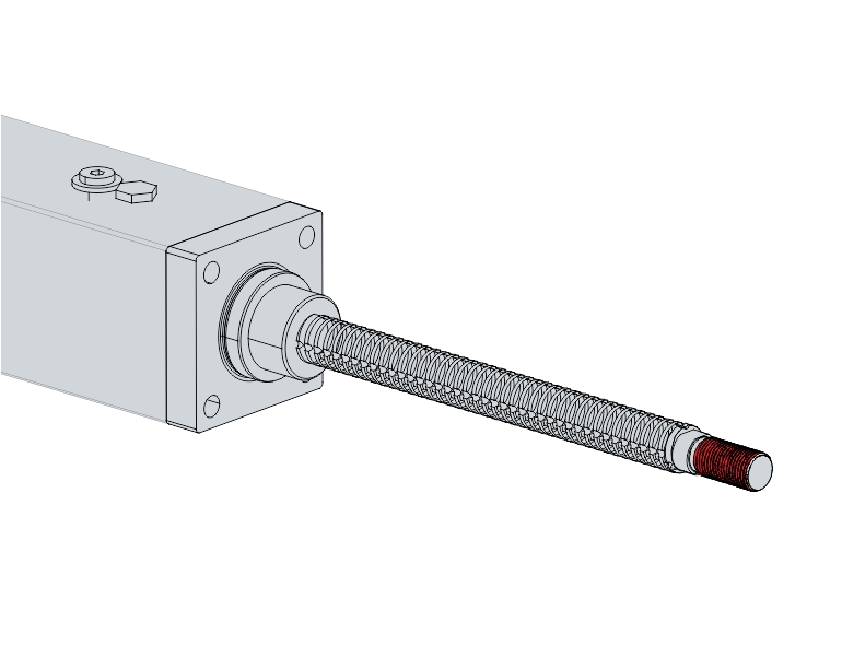
Attachment of the application to the end of the spindle
The application can be connected to the electric cylinder via the external thread at the end of the spindle. The dimensions can be found in the table below.
The wrench flat is used exclusively for fixing the spindle to prevent unwanted torque being introduced into the spindle as a result of assembly.
Size | AA3123 | AA3133 |
|---|---|---|
External thread at spindle end | M12 x 1.25 | M16 x 1.5 |
available thread length [mm] | 24 | 32 |
Width across flats | 13 | 17 |
Assembly of fasteners
The external thread of the spindle end is adapted to the common sizes of the pneumatic standard ISO 15552. Commercially available accessories such as rod ends, compensating couplings or clevises can be mounted on the spindle end to connect the electric cylinder to the application.
 | Mounting accessories on the spindle end This example shows the mounting of a rod end on the spindle. |

- ►Hold the spindle [1] with a suitable tool [2] at the wrench flat provided for this purpose while mounting the respective accessories [3].