Geometrische Definition
Planar Tracks werden schrittweise über aneinander gehängte Geraden, Kreisbögen und Punkte definiert. Die Verbindung zwischen diesen Elementen erfolgt automatisch über C2-stetige Interpolation („Verschleifungen“).
- Geraden werden über einen Start- und einen Endpunkt definiert, siehe AppendLine.
- Kreisbögen werden über einen Start-, einen End- und einen Mittelpunkt definiert und durch Angabe der Richtung in oder gegen den Uhrzeigersinn, siehe AppendCircle.
- Positionen werden nur über einen Punkt definiert, siehe AppendPosition.
Beispiel
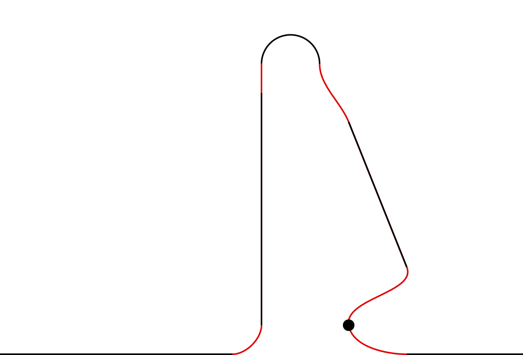
Im folgenden Beispiel sind die automatisch generierten Teile des Tracks in rot dargestellt.
PROGRAM MAIN
VAR
    track : MC_PlanarTrack;
    pos1, pos2 : PositionXYC;
    center : PositionXY;
    state : UDINT;
END_VAR
CASE state OF
0:
pos1.SetValuesXY(0, 0);
pos2.SetValuesXY(400, 0);
track.AppendLine(0, pos1, pos2);
pos1.SetValuesXY(450, 50);
pos2.SetValuesXY(450, 450);
track.AppendLine(0, pos1, pos2);
pos1.SetValuesXY(450, 500);
pos2.SetValuesXY(550, 500);
center.SetValuesXY(500, 500);
track.AppendCircle(0, pos1, pos2, center, TRUE);
pos1.SetValuesXY(600, 400);
pos2.SetValuesXY(700, 150);
track.AppendLine(0, pos1, pos2);
pos1.SetValuesXY(600, 50);
track.AppendPosition(0, pos1);
pos1.SetValuesXY(700, 0);
pos2.SetValuesXY(900, 0);
track.AppendLine(0, pos1, pos2);
END_CASE