Introduction
A cam plate editor is used to design the motions for a cam plate.
The cam plate editor is a flexible tool that provides optimum user support. The responsibility for the choice of parameters lies with you (the user). You should check carefully whether the start and end points meet the specification. The graphic display options provide optimum support for controlling velocities, accelerations and jerk.
Notwithstanding the wide range of options, please bear in mind the limits to possible motions imposed by physical constraints.
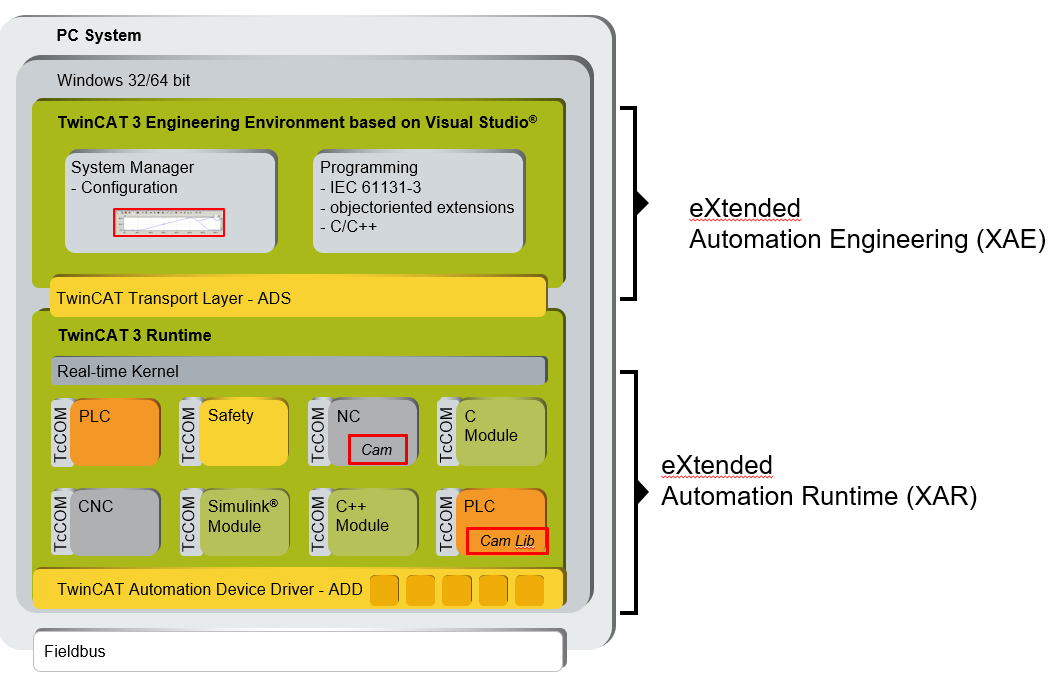
The CAM Design Tool is the cam plate editor of TwinCAT. It is integrated into the XAE engineering environment based on Visual Studio™. In the user interface it can be found under the System Manager (see diagram).
Cam plates that have been designed with the tool are stored in the respective project file. When the system is started, the cam plates are automatically transferred to the eXtended Automation Runtime (XAR).
eXtended Automation (XA) architecture
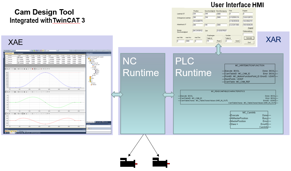
In XAR, the NC includes the functionalities required for coupling cam plates. These extensive functionalities can be called by the PLC with the TC-NC Camming library (TF5050). In addition to the standard function blocks of PLC Open, the library also contains compatible function blocks with extended functionalities. The following overview illustrates the options available through interaction of the CAM Design Tool with the NC and the PLC.
It is also possible, for example, to upload cam plates generated by the PLC, which were loaded into the NC via a function block, into the CAM Design Tool.
A user interface (HMI) can be connected via the PLC.
Generate CAM offline: CAM Design Tool | Generate CAM online: PLC Code |
|---|---|
Engineering: For designing a cam plate.
| PLC: For use in the production machine.
|
Information about the TF5050 PLC library can be found here.
PLC open Motion Control
The function blocks listed in the PLC library are based on:
Technical Specification
- PLCopen - Technical Committee 2 - Task Force
- Function blocks for motion control
Create project
 | A license is required to access the full functionality of the TE1510 CAM Design Tool, see Licensing. |
The cam plate editor integrated in TwinCAT 3 can be found in a Twin CAT project under MOTION > Tables.
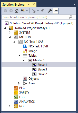
Here you can insert additional Masters and below that corresponding Slaves by right-clicking.
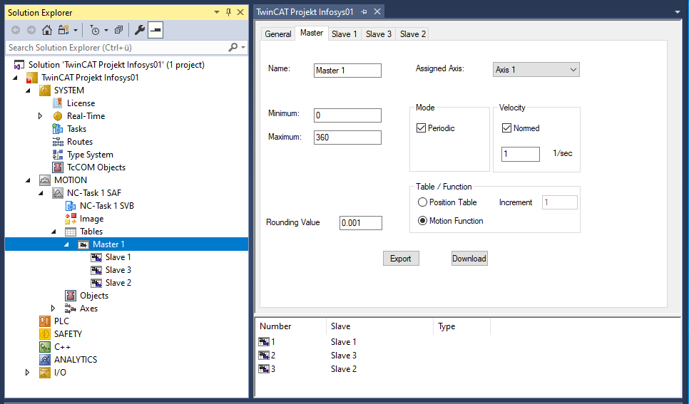
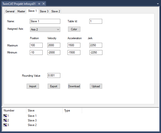
Click the Master in the structure tree to open the property pages. Not only the properties of the Master but also those of the associated Slaves can be set on these pages.
The general procedure for designing a cam plate is based on VDI Guideline 2143. The rough design of the motion - the motion plan - defines the start and end points of the motion section. However, the cam plate editor does not differentiate between the motion sketch and the motion diagram containing the detailed motion description.
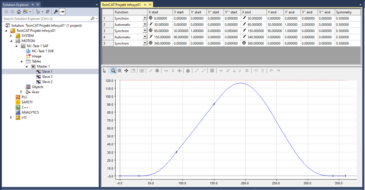
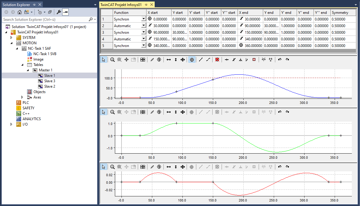
The user's interface to the cam plate editor is largely graphic. Following interactive graphic entry of the points in the graphic window, the co-ordinates of the points are displayed in the table window above it.
New points can only be inserted in the graph, and it is only possible to delete existing points via the graph. The properties of the points - the co-ordinate values or their derivatives - can also be interactively manipulated in the table window.
The following parameters can be displayed in the graphical area:
- position,
- velocity,
- acceleration,
- jerk.
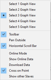
Change display
- The mouse pointer is in the graphic window.
- 1. Right-click.
- 2. Select the desired views in the menu window.
- For example, a separate graphic window is created for each derivative.