Advanced settings (Tc Advanced)
The advanced settings can be used to set parameters that affect the execution and call behavior of the module and also the display and properties of the exported block diagram:
Execution behavior of the generated module
In TwinCAT 3, a Simulink module can be called directly from a cyclical real-time task or from another TwinCAT module, e.g. a PLC. The behavior of the generated module class can be parameterized in Simulink under Tc Advanced. To specify individual module instances behavior that differs from the class behavior, the execution type can be adjusted in the TwinCAT 3 development environment via the TcCOM parameter list in the Parameter (Init) tab or via the parameter range of the block diagram.
Configuration of the default settings in Simulink
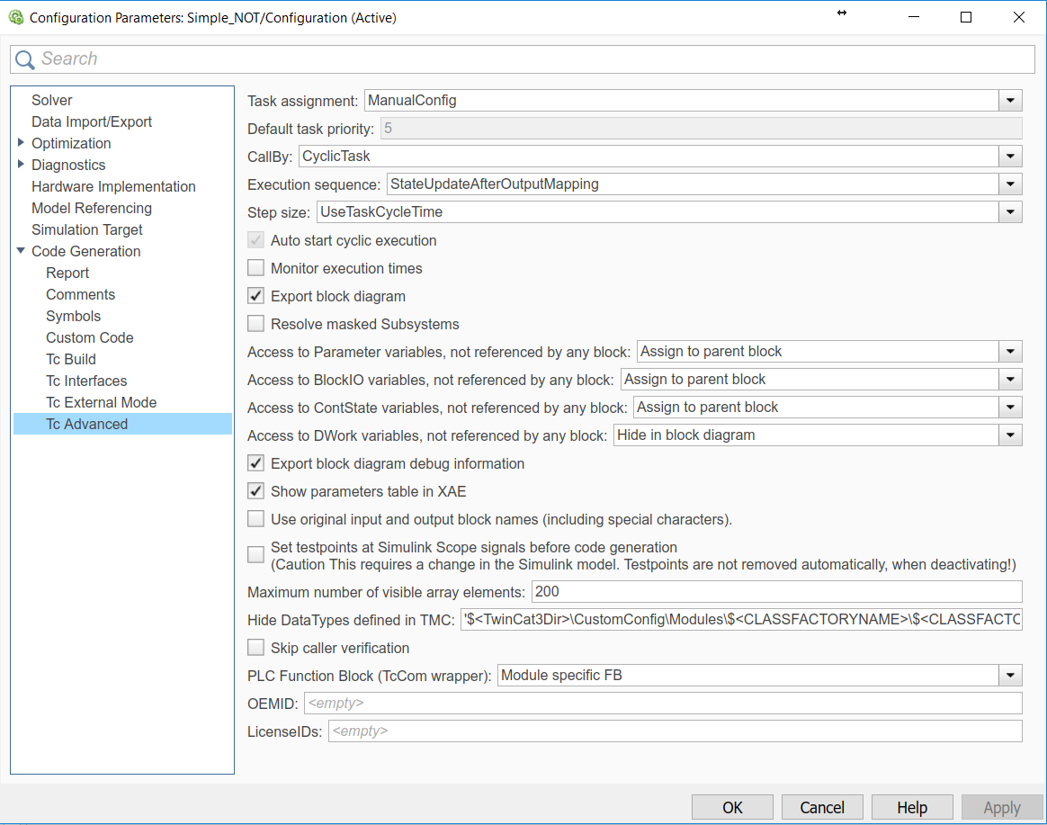
The default values of the call parameters can be configured in the Simulink coder settings, in order to reduce the parameterization effort for the individual objects (module instances):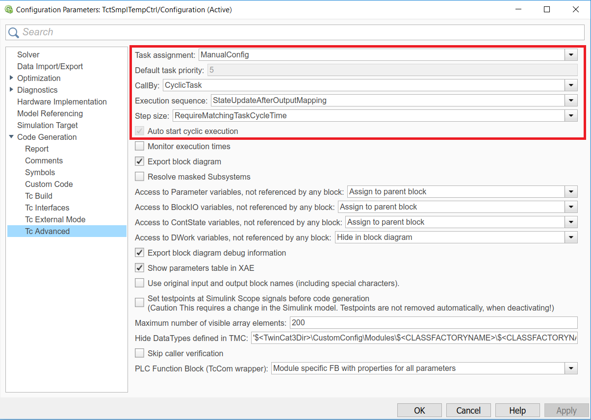
Task assignment
The assignment type for a TwinCAT task can be defined under Task assignment.
"Depend On" setting | Description |
|---|---|
Manual Config | The tasks can be assigned manually in the context table, by selecting or entering the object IDs of the tasks in the Task column. The selected tasks must meet all the criteria that were configured via the "Call parameters" |
Parent Object | Can only be used if the parent node of the module instance is a task in the project tree. In this case, the parent object is used as cyclic caller of the module. |
Task Properties | The tasks are automatically assigned to the module when the cycle time and the priority correspond to the values specified in Simulink. If there is no corresponding task, new tasks can be created and parameterized as required under the node "System Configuration -> Task Management". |
If the Task properties option is active, the priority of the corresponding task must be specified.
Cyclic call
If the value "CyclicTask" was set for the call parameter "CallBy", all task cycle times are verified when the module starts. The conditions for the cycle times of the associated tasks can be specified via the call parameter "Step size". If all cycle times meet their conditions, the module can start. Otherwise the module start and the TwinCAT runtime terminate with corresponding error messages.
Call from another TwinCAT module
If the call parameter "CallBy" was set to the value "Module", the assigned tasks do not call the module automatically. To call the generated TcCOM module via another module instead, the interfaces of that module can be accessed. This can be done from a C++-module or from a TwinCAT PLC, as shown in "Calling the generated module from a PLC project".
Execution order
In modules that were created with TE1400 from version 1.1, an execution order can be specified, in order to optimize the jitter and the response times for the respective application. Older versions use always the order "StateUpdateAfterOutputMapping". The following table illustrates the advantages and disadvantages of the supported call sequences:
- IoAtTaskBegin
 - Longest response time of all options
+ Smallest possible jitter in response time - StateUpdateAfterOutputMapping
 + Shortest response time
o Average jitter in response time
 | Results from "Minor Time Steps" are transferred via ADS Signal values transferred via ADS may differ from the values that were copied to other process images via "output mapping". The reason is that "State update" may overwrite values, depending on the selected solver. For further information see Transfer of the results from "Minor Time Steps". |
- StateUpdateBeforeOutputUpdate
 o Average response time
- largest jitter in the response time, since dependent on execution times for "State update" and "Output update
Step size adjustment (step size)
The behavior of the TcCOM that was generated with regard to the step size (corresponding to the cycle time in TwinCAT) is defined here.
- RequireMatchingTaskCycleTime
The module expects the "Fixed Step Size" specified in Simulink as cycle time for the allocated task. If another cycle time is set, the TcCOM start sequence is aborted with an error message. Multitasking modules expect that all allocated tasks were configured with the associated Simulink sample time. - UseTaskCycleTime
The module enables cycle times, which differ from the "Fixed Step Size" specified in Simulink. In multitasking modules, all task cycle times must match the corresponding Simulink sample times. If the cycle time deviates from the Simulink sample time, a warning is issued in TwinCAT indicating the deviation. - UseModelStepSize
The module uses the sample time set in Simulink for all internal calculations. This setting is primarily intended for use in simulations within the TwinCAT environment and can be used for accelerated or slowed-down simulation.
Auto start cyclic execution
If this option is enabled (default), the TcCOM module is set to OP state on startup, and the generated model code is executed directly. If this option is disabled, the module is also set to OP state, but the model code is not executed. In the instantiated module this option can be found in the “Parameter (init)” tab and in the parameter range of the block diagram under "Module parameters" as variable "ExecuteModelCode", where it can also be adjusted.
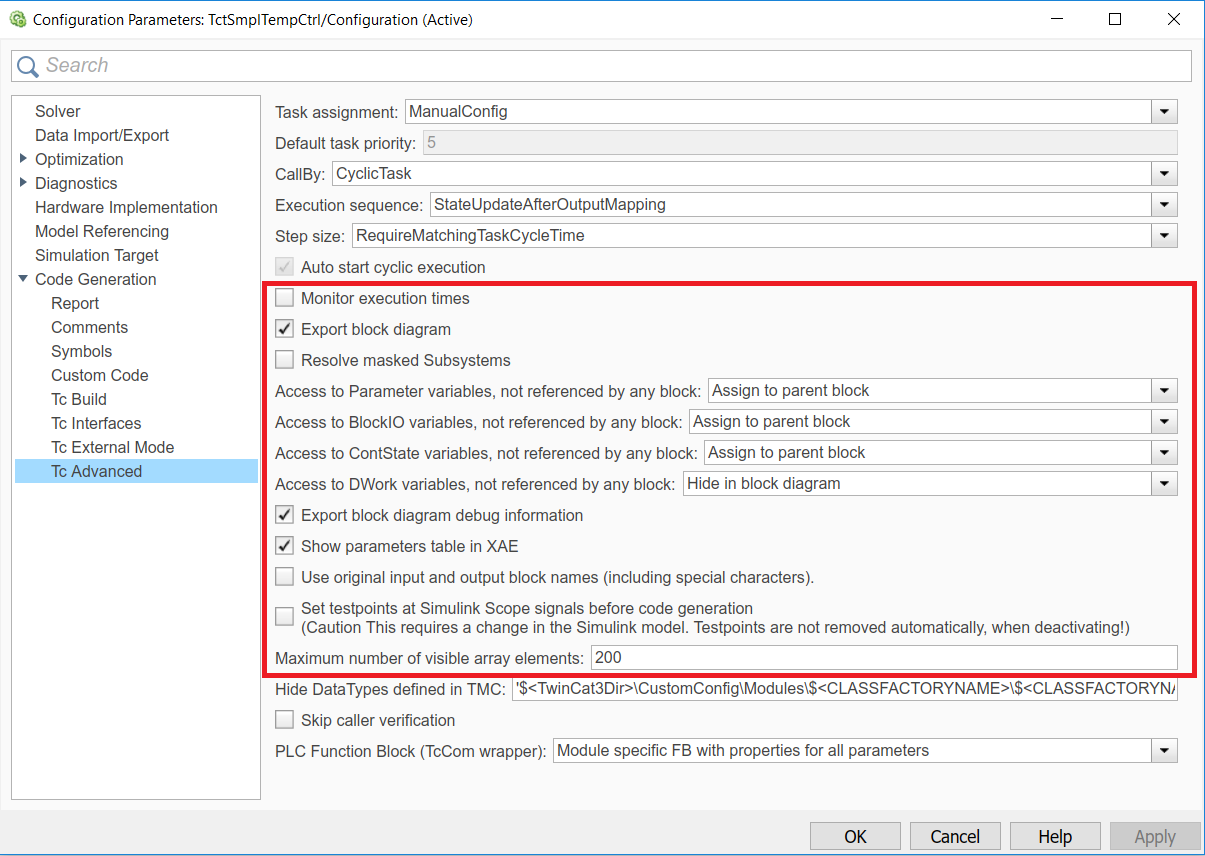
Adapting the display, debugging and parameterizability
Modules generated from Simulink offer a wide range of options for parameterizing the module and model parameters, even after code generation and instantiation. The parameterization options can be adjusted before the code generation, so that in the development phase debugging options are enabled and parameters of masked subsystems are resolved, which are to be hidden in the release version. The use of modules in TwinCAT 3 requires a display that can be configured according to requirements. For example, debugging information can be included in the block diagram export.
The following coder parameters enable adaptation of the block diagram export, the parameter and signal representation, and advanced functions:
Parameters | Description | Default value | |
|---|---|---|---|
Monitoring execution times | TRUE | The execution times of the TC module are calculated and made available as ADS variable for monitoring. | FALSE |
FALSE | Calculation of execution times disabled. | ||
Export block diagram | TRUE | The Simulink block diagram is exported and displayed in XAE under its "Block Diagram" tab once the module has been instantiated. | TRUE |
FALSE | The Simulink block diagram is not exported, and the "Block Diagram" tab is not displayed in XAE. | ||
Resolve masked Subsystems | Only relevant if "Export block diagram"=TRUE. | FALSE | |
TRUE | Masked subsystems are dissolved. All contents of masked subsystems are visible to users of the generated module in XAE. | ||
FALSE | Masked subsystems are not resolved. The contents of the masked subsystems are not visible to users of the generated module. | ||
Access to VariableGroup, not referenced by any block | Assign to parent block | Variables of this group, which belong to a block within an unresolved subsystem, are assigned to the next higher, visible subsystem. |
|
Hide in block diagram | Variables of this group, which cannot be allocated to a Simulink block, are not displayed in the block diagram. | ||
Hide, No access | Variables of this group, which cannot be allocated to a Simulink block, are hidden and made inaccessible. This is only possible, if "No DataArea" was selected for the process image of this variable group (configuration in Simulink). | ||
Export block diagram debug information | TRUE | Debugging information generated for the block diagram enables allocation of row numbers in the generated code to displayed blocks. Required for debugging. | TRUE |
FALSE | No debugging information is generated | ||
Show parameter table in XAE | TRUE | The "Parameter (Init)" tab is displayed in XAE and enables parameterization of the module via the parameter list. | TRUE |
FALSE | The "Parameter (Init)" tab is not displayed in XAE. | ||
Use original input and output block names | FALSE | Inputs and outputs of the module have the names that were created by the Simulink Coder as variable names. Spaces and special characters are not allowed. | FALSE |
TRUE | Inputs and outputs of the module have the names that were used in the Simulink model. The names may include spaces and special characters. | ||
Set testpoints at Simulink Scope signals before code generation |
| Scope blocks are ignored by the Simulink coder, i.e. the signals are generally not available in the generated TwinCAT module and cannot be displayed. To force the generation of variables for these signals, test points can be defined in the Simulink model. This parameter can be used to automatically create test points for all scope input signals. |
|
Maximum number of visible array elements |
| Specifies the maximum number of array elements to be displayed in the TwinCAT development environment. Larger arrays cannot be opened, and the elements cannot be linked individually, for example. |
|
Hide Datatypes defined in TMC
In each TMC file the required data types are specified and notified in the system through import in TwinCAT 3. The data types are assigned a unique GUID. Accordingly, the GUID remains unchanged if a TMC file is re-imported in which a data type has not changed. If enums or structures are used, for example, changes (e.g. additional model parameters in a structure) may result in the data type name of the modified data type and the previous data type being identical, with different GUIDs. This unique assignment via GUIDs is not available in the PLC, where the data type name is used for identification. If a TcCOM instance is called from the PLC, a mechanism must be provided that prevents this kind of ambiguity.
The Hide Data Types defined in TMC ensures that the last imported TMC or its data type names and data types are used for the PLC. Any existing data type names with other data types are hidden for the PLC. See also How do I resolve data type conflicts in the PLC project?.
Skip caller verification
This option disables queries when calling a TcCOM from the PLC, see Calling the generated module from a PLC project. This leads to faster processing of the module call. On the other hand, the user must make sure that the call is executed correctly and from the correct context.
This option should only be activated if it is necessary for performance reasons, and if the project has previously been tested with activated queries.
PLC Function Block
The POU type for calling a Simulink object from the PLC can be defined in more detail here. A more detailed description can be found under "Calling the generated module from a PLC project".
OEM license check
Optionally, a generated TcCOM can be linked to an OEM license. This OEM license is checked when starting TcCOM (besides the Beckhoff runtime license TC1220 or TC1320) in TwinCAT 3. If no valid license is available, the module does not start up and an error message appears.
How to create and manage OEM certificates can be found under TwinCAT3 > TE1000 XAE > Technologies > Security Management.
In Simulink, you can insert the OEM License Check by naming your OEM ID and your license ID or multiple license IDs to be queried. You can find your OEM ID in the Security Management Console (Extended Info activated). The license ID can be viewed by double-clicking on the corresponding license entry in TwinCAT under System > License. Both IDs are also included in the generated License Request File when a Request File is generated with your OEM license.
| Note GUID form The IDs to be entered must be transferred as a string in GUID form, i.e. in Simulink the data must be entered in quotation marks. No spaces are allowed in the specifications. |
Sample entry:
OEM ID: '{B0D1D1B7-99AB-681G-F452-F4B3F1A993C0}'
License ID: 'Name1,{6B4BD993-B7C3-4B72-B3D1-681FE7DDF3D1}'