Filter set properties
Some of the properties of the filter sets are independent of the filter and the filter type. These generally applicable filter set properties are described in more detail here.
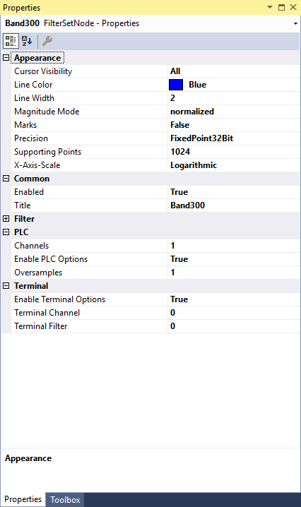
Appearance:
Cursor Visibility: | Specifies whether the drag & drop cursor for the cut-off frequency is displayed. |
Line Color: | Specifies the color of the filter set. |
Line Width: | Line width of the chart. Line width 1 causes the lowest computing time. |
Magnitude Mode: | You can choose between two modes here. The default mode is normalized and corresponds to the magnitude of the frequency response. In dB mode, the frequency response is displayed with logarithmic scaling. |
Marks: | Indicates whether the interpolation points of the characteristic curve should be displayed. |
Precision: | The filter coefficients can be calculated with different precision. FixedPoint32Bit is the default mode and is required for the measuring terminals, since they calculate using fixed-point arithmetic. Alternatively, FixedPoint64Bit mode (higher precision) is to be selected if the coefficients are to be transferred to the PLC. |
Supporting Points: | Number of interpolation points in the Bode Plot. |
X-Axis-Scale: | The frequency axis can be scaled logarithmically or linearly. |
Common:
Enabled: | With this property you can activate and deactivate the display of the filter curve. |
Title: | Specifies the name of the filter set. |
PLC:
Channels: | Number of channels with which the filter structure is to be configured. |
Enable PLC Options: | Must be true if a filter is to be transferred to the PLC. |
Oversamples: | Number of oversamples with which the filter structure is to be configured. |
Terminal:
Enable Terminal Options: | Must be true if a filter is to be transferred to the measuring terminal according to the channel and filter number. |
Terminal Channel: | Specifies the channel number. |
Terminal Filter: | Specifies the filter number. |