Front side and operating elements
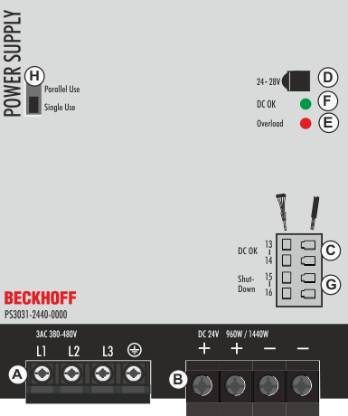
Input terminals (screw terminals)
Designation (A) | Description |
|---|---|
L1, L2, L3 | Mains input L1, L2, L3 |
| PE input (protective conductor) |

Output terminals (screw terminals, two contact pins per pole)
Designation (B) | Description |
|---|---|
+ | two identical positive poles, positive output |
- | two identical negative poles, negative output |
DC-OK relay contact (spring-loaded terminals)
Designation (C) | Description |
|---|---|
13 / 14 make contact | The DC-OK relay contact is synchronized with the DC-OK LED |
Potentiometer for the output voltage
Designation (D) | Description |
|---|---|
Potentiometer cover | Open the flap to adjust the output voltage. |
Overload LED
Designation (E) | Description |
|---|---|
LED red | On when the voltage at the output terminals is <90% of the set output voltage, or in the event of a short circuit in the output. Flashes when the switch-off has been activated or when the device has switched off due to overtemperature. The input voltage is always required. |
DC-OK LED
Designation (F) | Description |
|---|---|
LED green | On when the voltage at the output terminals is >90% of the set output voltage. |
Shutdown input
Designation (G) | Description |
|---|---|
Shutdown input | Input for shutdown and remote control |
Selector switch for "Parallel Use" / "Single Use" mode
Designation (H) | Description |
|---|---|
Selector switch for "Parallel Use" / "Single Use" mode | Set the jumper to "Parallel Use" mode if power supplies are connected in parallel to increase the output power. In order to distribute the load current between the individual power supplies, "Parallel Use" mode regulates the output voltage so that the idle voltage is approx. 4% higher than at nominal load. See also chapter "Parallel Use" for power increase. A missing jumper corresponds to "Single Use" mode. |
LED displays | Overload LED | DC-OK LED | DC-OK contact |
|---|---|---|---|
Normal mode | OFF | ON | Closed |
During extra power | OFF | ON | Closed |
Overload (Vout < 90%) | ON | OFF | Open |
Short circuit at output | ON | OFF | Open |
Temperature switch-off | flashes | OFF | Open |
Shutdown input active | flashes | OFF | Open |
No input power | OFF | OFF | Open |