Installation positions
Install the device onto a DIN rail with the input terminals on the bottom of the device (see following fig. Mounting position A (Standard mounting position))
The test environment is set up installing wiring ducts with a depth of 80 mm with clearances seen in the following table.
Minimum installation clearances
Output power in relation to the nominal output | Minimum installation clearances (mm) | ||
|---|---|---|---|
top | bottom | Left and right side | |
< 50% | 40 | 20 | 0 |
≥ 50% | 40 | 20 | 5 |
≥ 90% | 40 | 20 | 15 |
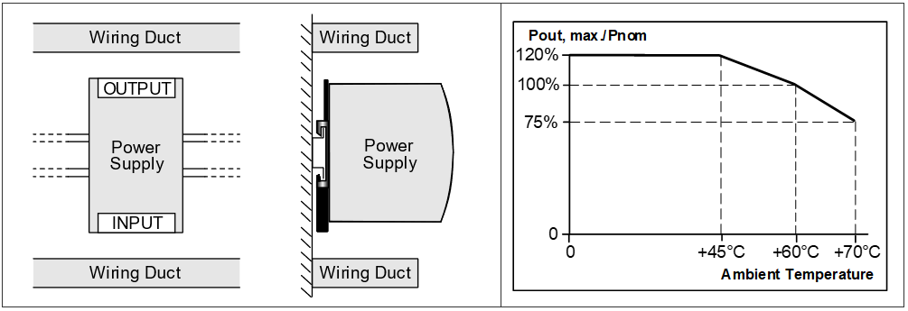
The following curve gives an indication for the allowed output power for altitudes up to 2000 m at an input voltage range of 100 - 240 Vac.