Output
The output provides an SELV/PELV nominal voltage that is electrically isolated from the input voltage.
The output is designed to supply any type of load, including capacitive and inductive loads. If very large capacitors, such as EDLCs (electrical double-layer capacitors or "UltraCaps") with a capacitance > 0.3F are connected to the output, the device can charge the capacitor intermittently.
The output is electronically protected against overload, no-load and short circuit. In the event of a protection event, audible noises may occur.
Output voltage | Nom. | 24V |
|
Adjustment range | Min. | 24-28V | Guaranteed value |
Max. | 30.0V | This is the maximum output voltage that can occur in the end position of the potentiometer in clockwise direction due to tolerances. It is not a guaranteed value that can be achieved. | |
Factory settings | Typ. | 24.1V | ±0.2% at full load (cold device) |
Line regulation | Max. | 10 mV | Between 85 and 300Vac |
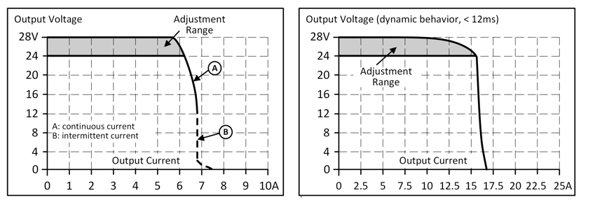
Load regulation | Max. | 50 mV | Between 0 and 6A, static value, see Fig. Output voltage over output current, typ. |
Residual ripple and ripple voltage | Max. | 50mVss | Load >0.2A, bandwidth 20Hz to 20MHz, 50Ohm |
Max. | 200mVss | Load <0.2A, bandwidth 20Hz to 20MHz, 50Ohm | |
Output current | Nom. | 6A1) | At 24V and an ambient temperature below 45°C, see Fig. Output current over ambient temperature |
Nom. | 5A | At 24V and 60°C ambient temperature, see Fig. Output voltage over output current, typ. | |
Nom. | 3.8A | At 24V and 70°C ambient temperature, see Fig. Output current over ambient temperature | |
Nom. | 5.1 A1) | At 28V and an ambient temperature below 45°C, see Fig. Output current over ambient temperature | |
Nom. | 4.3A | At 28V and 60°C ambient temperature, see Fig. Output voltage over output current, typ. | |
Nom. | 3.2A | At 28V and 70°C ambient temperature, see Fig. Output current over ambient temperature | |
Safety | Typ. | 15A | For at least 12ms once every five seconds, see Fig. Dynamic output current capacity, typ. |
Overload behavior |
| Continuous current | Output voltage > 13Vdc, see Fig. Output voltage over output current, typ. |
| Hiccup mode 2) | Output voltage < 13Vdc, see Fig. Output voltage over output current, typ. | |
Short circuit current | Max. | 7.2A | Continuous current, see Fig. Output voltage over output current, typ. |
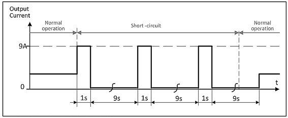
Typ. | 9A | Intermittent current peak value for typ. 1s | |
Max. | 3.5A | RMS value of current, load impedance 50mOhm, see Fig. Short-circuit at output | |
Output capacity | Typ. | 1800μF | Included in the power supply |
Load feedback | Max. | 35V | The device is resistant to load feedback and will not indicate a malfunction if a load is feeding voltage back into the power supply. It does not matter whether the power supply is switched on or off. The absorbed energy can be determined by means of the built-in large-size output capacitor. |
1) Up to +70°C this power / current can be called up for a duty cycle of 10%, i.e. no longer than 1 minute every 10 minutes.
2) In the event of heavy overload (when the output voltage drops below 13V), the power supply provides continuous output current for 1s. The output is then switched off for about 9 seconds before a new switch-on attempt is automatically made. This cycle is repeated as long as the overload persists. After the overload has been rectified, the device will operate normally. See Fig. Short circuit at output